


DCD-24 User Manual (rev 1.00)
Page 13
Page 12
DCD-24 User Manual (rev 1.00)
Front Panel Replica
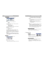
The main section of the HTML page is a functional replica of the front panel.
The front panel switches and web page buttons operate in parallel, although web
page clicks are inhibited while any front panel key is being pressed.
Menus are accessed by clicking on the [
set
up
] button. In SET UP mode, a yellow
LED bar is added under the active set up column.
Unlike the front panel switch, the [
view
]
button is click-on, click-off.
The page is refreshed every second, plus immediately after any button on the
page is clicked.
14. Firmware Updates
14.1. FIRMWARE UPDATE PAGE
Clicking on the UPDATE FIRMWARE button of the main HTML page takes you to
another page, strictly dedicated to uploading new firmware.
To update your firmware, click on the BROWSE button and select the firmware file
on your hard disk (.upld). Then click UPLOAD. The normal programming sequence
will follow.
Messages in the Upload Status box at the bottom of the page keep you informed of
the progress, including error messages.
14.2. COMPLETE VS SOFTWARE
When downloading firmware updates from the Brainstorm website, 2 types of
image files are available: ‘complete’ and ‘software’.
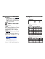
The DCD-24 FLASH memory is divided in several sections, for the parameters settings,
the application software, the Loader software and the FPGA image. The diagram
below shows the difference between ‘complete’ and ‘software’ updates.
The major software rev number will change whenever the FPGA or LOADER changes.
This means that:
- updates between any 1.xx version can be “software” only,
- updates from, for example, 1.xx to 2.xx must be a “complete” update.
14.3 PROGRAMMING SEQUENCE
There are 3 steps in the normal programming sequence: Upload, Verify and Program.
• Step 1: the file is uploaded. A message indicates ‘UPL’ followed by a percent
-
age complete value.
• Step 2: the file is checked, indicated by a ‘TEST’ message, then ‘PASSED’.
→
• Step 3: the file is programmed into the DCD-24 flash memory. A message
indicates ‘PRG’ followed by a percentage complete value.
Note: During the 3rd step (programming), Ethernet is internally disconnected.
Reboot
• At the conclusion of a Flash programming sequence following the upload of
a ‘complete’ image file, the display slow flashes “REBOOT” to indicate that a
reboot is required. Turn power off then back on.
• After uploading a ‘software’ image file, the DCD-24 automatically reboots.
14.4 PROGRAMMING ERRORS
A. Upload Error
An error during the upload step should always be
recoverable since the programming hasn’t started
yet. Simply start the Upload again.


