Gas
Valve
Repla
c
eme
n
t
Pro
c
e
d
ure
St
e
p
1
.
Po
s
itio
n
mai
n
pow
er
s
witch
to
“O
FF
”
.
St
e
p
2
.
D
i
s
co
nne
ct
(u
n
p
l
u
g
)
wat
er
h
e
at
er
f
r
om
120
vo
l
t
pow
er
s
ou
r
c
e
.
St
e
p
3
.
T
u
rn
off
g
a
s
s
upp
l
y
to
wat
er
h
e
at
er
.
St
e
p
4.
U
n
-l
atch
&
re
mov
e
s
u
rr
ou
n
d
cov
er
f
r
om
top
of
h
e
at
er
.
St
e
p
5
.
F
r
om
th
e
g
a
s
va
l
v
e
,
di
s
co
nne
ct
th
e
g
a
s
co
nne
ctio
n
,
P
V
C
damp
er
a
sse
mb
l
y,
s
i
l
ico
ne
tubi
n
g
a
n
d
wi
re
ha
rness
.
St
e
p
6
.
R
e
mov
e
th
e
2
g
a
s
va
l
v
e
mou
n
ti
n
g
s
c
re
w
s
(
T
o
r
x
bit)
l
ocat
e
d
at
th
e
11
:
00
O
-
c
l
oc
k
&
5
:
00
O
-
c
l
oc
k
po
s
itio
n
o
n
th
e
v
en
tu
r
i
mou
n
ti
n
g
f
l
a
n
g
e
a
n
d
re
mov
e
g
a
s
va
l
v
e
f
r
om
wat
er
h
e
at
er
.
St
e
p
7
.
R
e
mov
e
a
n
y
res
idua
l
g
a
s
k
e
t
mat
er
ia
l
f
r
om
b
l
ow
er
a
n
d
v
en
tu
r
i
mou
n
ti
n
g
f
l
a
n
g
e
.
St
e
p
8
.
I
ns
ta
ll
ne
w
g
a
s
va
l
v
e
with
ne
w
g
a
s
k
e
t p
r
ovid
e
d
.
S
e
cu
re
g
a
s
va
l
v
e
i
n
p
l
ac
e
u
s
i
n
g
s
c
re
w
s
f
r
om
s
t
e
p
6
.
St
e
p
9
.
R
e
co
nne
ct
P
V
C
damp
er
a
sse
mb
l
y,
g
a
s
s
upp
l
y,
wi
re
ha
rness
a
n
d
s
i
l
ico
ne
tubi
n
g
to
g
a
s
va
l
v
e
.
T
u
rn
o
n
g
a
s
s
upp
l
y
to
h
e
at
er
a
n
d
ch
e
c
k
fo
r
g
a
s
l
e
a
k
s
,
re
pai
r
a
n
y
g
a
s
l
e
a
k
s
fou
n
d
.
St
e
p
10
.
R
es
to
re
120
vo
l
t
pow
er
s
upp
l
y
to
wat
er
h
e
at
er
a
n
d
co
n
fi
r
m
p
r
op
er
op
er
atio
n
fo
ll
owi
n
g
th
e
l
i
g
hti
n
g
i
ns
t
r
uctio
ns
o
n
th
e
l
i
g
hti
n
g
i
ns
t
r
uctio
n
l
ab
e
l
o
r
th
e
l
i
g
hti
n
g
i
ns
t
r
uctio
n
l
ocat
e
d
i
n
th
e
i
ns
ta
ll
atio
n
a
n
d
op
er
ati
n
g
i
ns
t
r
uctio
n
ma
n
ua
l.
St
e
p
11
.
R
e
p
l
ac
e
s
u
rr
ou
n
d
cov
er
o
n
top
of
wat
er
h
e
at
er
.
W
AR
NIN
G
120 volt potential exposure. Isolate the
appliance and reconfirm power is
disconnected using a multi-meter.
37
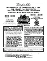
B
lower
B
lower
/
gas
v
al
v
e
gas
k
et
G
as
v
al
v
e
assembl
y
V
enturi
mounting
flange
G
as
v
al
v
e
mounting
screws
(
X2
)
37