background image


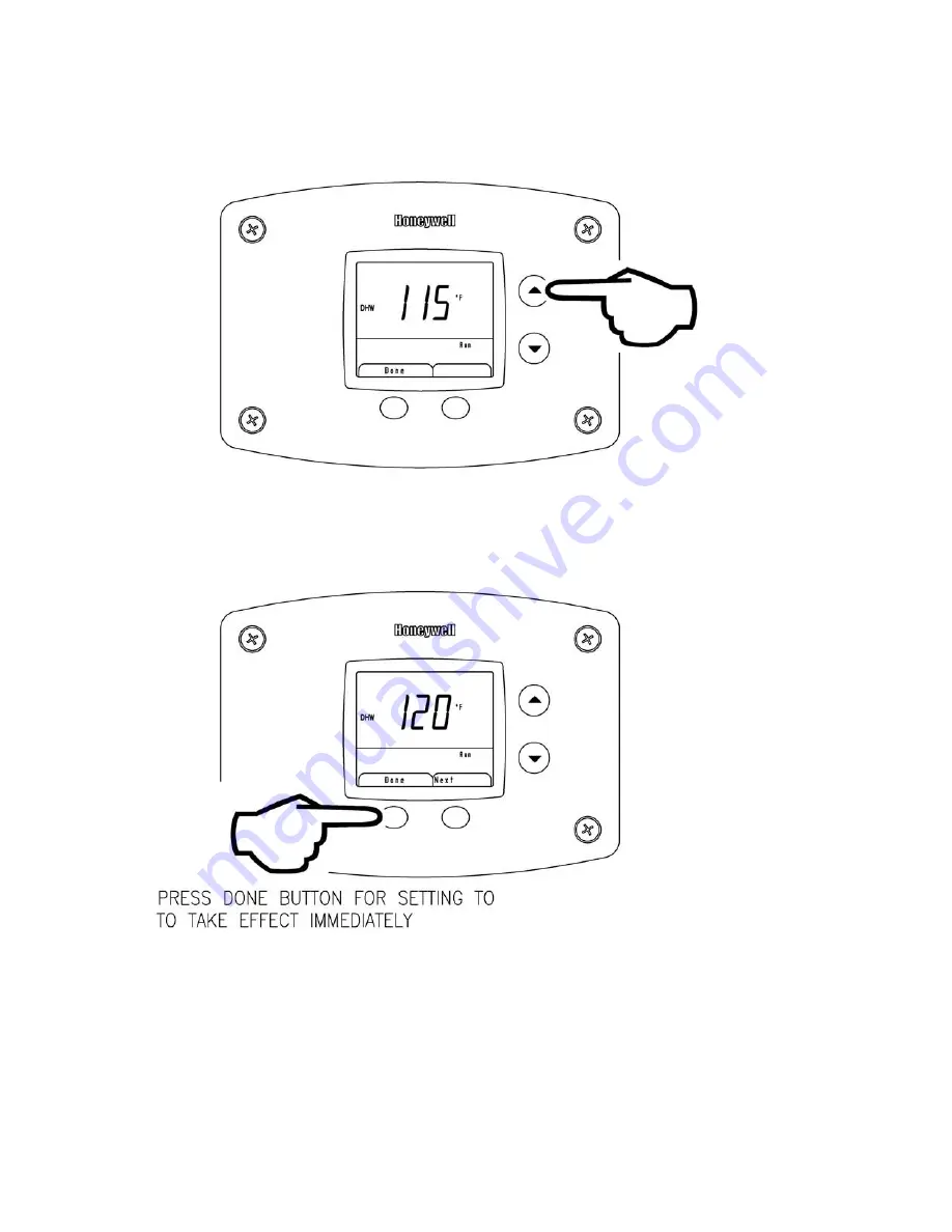
To Increase Setpoint Temperature: 

 
Step 1:  Depress and hold “Temperature Up” button until desired setpoint temperature appears in the display.   


Step 2:  Press “DONE” button for new setting to take effect immediately.  If the “DONE” button is not pressed, the new 
temperature setting will take effect in approximately 10 seconds.


Содержание 100T399-SOLA

Страница 1: ...not touch any electrical switch do not use any phone in your building Immediately call your gas supplier from a neighbor s phone Follow the gas supplier s instructions If you cannot reach your gas su...

Страница 2: ...f the water heater provides for setting and displaying the temperature setpoint and monitoring the status of the water heater Durable direct spark ignition system The temperature adjustment range is 7...

Страница 3: ...le that can have the power supply interrupted by a switch that is used to control lights or another appliance If wiring in conduit is required cut the line cord close to the control board and make the...

Страница 4: ...rod sparks to the burner and gas valve opens burner ignition 5 Flame signal confirmed 6 Blower remains at reduced speed for a short time to stabilize flame 7 Blower increases to full speed for full i...

Страница 5: ...it F or degrees Celsius C and the status of the water heater Standby or Run For energy efficient operation of your water heater the suggested initial temperature setting is 120 F 49 C During the winte...

Страница 6: ...highly recommended that the setpoint be adjusted to the lowest temperature possible for the needs of the installation Make sure the water heater control display is not in a public area that can resul...

Страница 7: ...d Temperature Up button until desired setpoint temperature appears in the display Step 2 Press DONE button for new setting to take effect immediately If the DONE button is not pressed the new temperat...

Страница 8: ...DONE button is not pressed the new temperature setting will take effect in approximately 10 seconds NOTICE Pressing the NEXT button instead of DONE will enter the display to show unused screens such a...

Страница 9: ...between F or C Press DONE when selection is complete Display will revert back to DHW setpoint NOTICE Pressing the NEXT button instead of DONE will enter the display to show RMT for Remote Firing Cont...

Страница 10: ...y indicating that the control cycled through the maximum number of ignition retries for ignition The control will make another 4 ignition attempts after the 15 minute waiting period 10 If the exhaust...

Страница 11: ...c Mode for 12 5 minutes after the last button press for viewing unless Done button is pressed to exit Diagnostic Mode Step 2 The display will show the flame sense current in microamps when the burner...

Страница 12: ...xt button and the display will show the temperature sensor reading Step 6 Press lower right Next button and the display will show the manual firing rate adjustment This function is not currently used...

Страница 13: ...ons Check to make sure the wiring connections on the control module from terminals J4 10 and J8 2 are connected together 62 Fan speed not proved Check the PWM wire harness connection from the blower t...

Страница 14: ...reattempt ignition after 15 minute waiting period Check gas valve wiring and gas valve operation during the ignition cycle If burner lights but quickly goes out check the flame sensor wire or the flam...

Страница 15: ...11592 11308 11032 10763 10502 10248 10000 9760 9526 80 9299 9078 8862 8653 8449 8250 8057 7869 7685 7507 90 7333 7165 7000 6839 6683 6531 6383 6238 6098 5961 100 5827 5697 5570 5446 5326 5208 5094 49...

Страница 16: ...16 Condensate Trap Elbow 17 Silicone hose 18 Outer Door Service Panel Specify model 19 Clip 20 NSF Escutcheon 21 Exhaust Pressure Switch 22 Nuts 23 Collector Limit Switch 24 Screw 6 32 x 3 8 25 Clean...

Страница 17: ...ition Specify model 3A Burner Ass y Specify model 16A Screw 8 32 x 1 4 RHCR 4A Blower Specify model 17A Gasket Flame Sensor 5A Silicone Hose 18A Flame Sensor 6A Burner Mounting Insert Gasket 19A Trans...

Страница 18: ...s pending Current Canadian Patents 2 092 105 2 107 012 2 108 186 2 112 515 2 143 031 2 239 007 2 262 174 2 314 845 2 409 271 2 476 685 2 504 824 2 548 958 CC Ignition Control Assembly 1C Control Mount...

Страница 19: ...19 NOTES...

Страница 20: ...20 NOTES...

Отзывы: