BOXER BHL-225 Скачать руководство пользователя страница 19

CAUTION

: Before disconnecting hydraulic lines, 

relieve all hydraulic pressure. Escaping hydraulic oil under pressure can have sufficient force to penetrate the skin 
causing serious personal injury. If injured by escaping hydraulic oil, seek medical attention immediately.


  CAUTION

: Do not operate the backhoe if the fittings leaking or if the hoses are damaged. A sudden line burst 

would cause the boom, or dipper arm bucket to drop suddenly, causing damaged to the tractor or    backhoe or injury to 
personnel. 


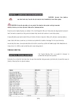
6.2 INITIAL BACKHOE OPERATION 


Before operating the backhoe, fully raise and lower the boom, arm, swing and stabilizers two or three times. Then raise the 
bucket  above  the  ground  and  cycle  the  bucket  cylinders  three  times.  Lower  the  bucket  to  the  ground.  Check  the  tractor 
hydraulic oil level and add as required.   
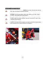
CAUTION: 

Before leaving  the machine, stop  the engine,  remove the key. Place all controls in neutral,    and 

either set the parking brake or place tractor in park as equipped. 


When possible keep cylinders in a retracted position when the backhoe is in use guard against rust and contamination which 
may  cause  damage  to  the  cylinder  rods  or  hydraulic  system.  Also,  lock  the  swing  and  boom  while  backhoe  is  being 
transported and storing for an extended period of time.   

6.3 COLD WEATHER OPERATION 


For smooth operation in cold weather, let the tractor warm up. Slowly cycle all of the cylinders several times to warm the oil 
in the hydraulic system. The backhoe may operate erratically until the hydraulic oil has warmed to operating temperatures.   

CAUTION

: Operate controls only when seated in the operator’s seat with seat belt on. 


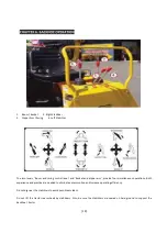
6.4 BACKHOE HYDRAULIC CONTROLS 


The backhoe hydraulic valve features 4 control levers. Refer to the diagram below for backhoe control functions. 

“Left” and 

“Right” are determined by the direction the operator is facing when seated in the backhoe. 


The Diagram is located on the rear of the control valve bracket and is visible when operating the valve.   

[18]   


Содержание BHL-225

Страница 1: ......

Страница 2: ...CKHOE MOUNTING 13 5 1 PTO CONNECTION BHF AND BHES MODELS 13 5 2 HYDRAULIC CONNECTION BHEF AND BHES MODELS 13 5 3 FITTING BACKHOE TO TRACTOR 13 5 4 REMOVE HACKHOE FROM TRACTOR 15 CHAPTER 6 BACKHOE OPER...

Страница 3: ...ackhoe Refer to the Safety Precautions section of this manual for information concerning safety consult your dealer for further information Serial Number and Location Serial Number and Location The se...

Страница 4: ...eeling Travel speed should be such that complete control and machine stability is maintained at all times Where possible avoid operation near ditches embankments and holes Reduce speed when turning cr...

Страница 5: ...ng someone When using a backhoe be alert of bucket boom and arm position at all times Only operators who have been specially trained in backhoe operation and fully understand this manual can operate t...

Страница 6: ...safety decals with new decals from your dealer 3 If a component with a safety decal s affixed is replaced with a new part ensure new safety decal s are attached in the same locations on the replaceme...

Страница 7: ...6...

Страница 8: ...7...

Страница 9: ...MIN Max hydraulic flow allowed 13MPA 13MPA Min hydraulic press Allowed 16MPA 16MPA Bucket digging force kg 1100 1700 Dipper arm digging force kg 850 1100 Item Service Service Interval Hydraulic System...

Страница 10: ...ents 1 Front Hose Dipper Arm 6 Hose Turning Cylinder 2 Long Hose Boom 7 Oil Return Cylinder 3 Control Valve DL F20L 8 Inlet Oil Hose Control Valve 4 Short Hose Boom 9 Inlet Hose Gear Pump 5 Rear Hose...

Страница 11: ...3 3 Backhoe Main Components 1 Bucket 7 Stabilizer 2 Dipper Arm 8 Swing Post 3 Boom 9 Main Frame 4 Bracket for Control 10 Sub A Frame 5 Tank 11 Boom Safety Lock Pin 6 Seat 10...

Страница 12: ...rate specified for your backhoe The flow may need to be reduced to an acceptable rate by throttling the engine RPM Adjusting the flow rate correctly could prevent sudden shock loads on the cylinders h...

Страница 13: ...overlap of 150mm in drive position Connect PTO shaft to tractor PTO output shaft and backhoe hydraulic pump shaft Check PTO shaft has suitable angle prior to operation Angle of PTO shaft universals m...

Страница 14: ...EF BHES models connect backhoe hydraulic hoses to tractor hydraulic remotes Refer to Photo 7 Lift boom stabilizer legs into transport mode fit boom safety pin and adjust 3 P L sway chains Refer to Pho...

Страница 15: ...to 2 Remove A frame lockout upper and lower bolts Refer to Photo 3 Remove A frame lockout bars Refer to Photo 4 Remove 2 piece solid top link Refer to Photo 5 Lower 3 P L onto 3 secure stands Refer to...

Страница 16: ...15...

Страница 17: ...e Backhoe if the fittings are leaking or if the hoses are damaged A sudden line burst would cause the boom to drop suddenly potentially causing death bodily injury or property damaged CAUTION Before d...

Страница 18: ...lar servicing We urge you to follow this advice 1 Read and understand this manual as well as the Tractor Operator s Manual 2 Remember and observe the safety precautions brought to your attention in th...

Страница 19: ...controls in neutral and either set the parking brake or place tractor in park as equipped When possible keep cylinders in a retracted position when the backhoe is in use guard against rust and contami...

Страница 20: ...m provide four simultaneous operations Both experience and practice are needed to eliminate excess motion and increase operating efficiency Do not dig near the stabilizers to avoid possible accident D...

Страница 21: ...ack and the place the lock pins through holes in swing frame and boom For models BHES and BHUS side shift boom carries to one side swing boom to opposite side and drop pin through holes in swing frame...

Страница 22: ...m in the same direction you are about to slide it the loading edge of the boom hitch plate with catch and dig in when you attempt to slide it across this will eventually wear out the slides or create...

Страница 23: ...izers could collapse Make all movements slow And gradual when practicing operation CAUTION Operate from backhoe operator s seat only Pay attention be ready to stop immediately in case Of emergency CAU...

Страница 24: ...23...

Страница 25: ...Hydraulic System Oil Level Check Daily 10 Hours Hydraulic System Oil Filter Replace Every 50 Hours Tyre Inflation Check Weekly 50 Hours Backhoe Pivot Points Lubricate Grease Daily 10 Hours Backhoe Hyd...

Страница 26: ...ion problems Determine the problem that best describes the operational problem being experience and eliminate the possible causes as listed by following the correction procedures 25 Model BHM 195 BHL...

Страница 27: ...nd correct hydraulic hose connections Stabilizer Legs Swing Boom Dipper Arm and Bucket Cylinders not working Hydraulic hoses to from control valve blocked Check for damage kinked hoses etc Backhoe con...

Страница 28: ...nd correct hydraulic hose connections Stabilizer Legs Swing Boom Dipper Arm and Bucket Cylinders not working Hydraulic hoses to from control valve blocked Check for damage kinked hoses etc Backhoe con...

Страница 29: ...level Check and replenish hydraulic fluid Hydraulic hoses connected improperly Check and correct hydraulic hose connections Stabilizer Legs Swing Boom Dipper Arm and Bucket Cylinders not working Hydr...

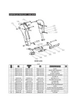
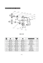
Страница 30: ...FRONT ARM 29...

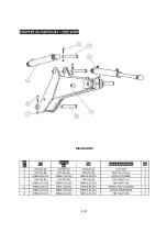
Страница 31: ...MAIN BOOM 30...

Страница 32: ...SWING JOINT 31...

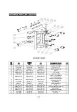
Страница 33: ...SIDE SHIEFT FRAME 32...

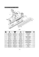
Страница 34: ...BASE 33...

Страница 35: ...OPERATION PANNEL AND OIL TANK 34...

Страница 36: ...SUPPORTING LEG 35...

Страница 37: ...SEAT 36...

Страница 38: ...BUCKET 37...

Страница 39: ...FRONT ARM ASSEMBLY 38...

Страница 40: ...MAIN BOOM 39...

Страница 41: ...40...

Страница 42: ...BOTTOM SEAT ASSEMBLY 41...

Страница 43: ...SWING POST ASSEMBLY 42...

Страница 44: ...SEAT 43...

Страница 45: ...th m 1 7 1 7 Swing angle for boom 180 180 Bucket turning angle 195 203 Bucket turning angle 0 02 0 035 Bucket width mm 15L MIN 25L MIN Min hydraulic flow req 25L MIN 40L MIN Max hydraulic flow allowed...

Страница 46: ...45...

Страница 47: ...ydraulic hoses connected improperly Check and correct hydraulic hose connections Stabilizer Legs Swing Boom Dipper Arm and Bucket Cylinders not working Hydraulic hoses to from control valve blocked Ch...

Страница 48: ...raulic hoses connected improperly Check and correct hydraulic hose connections Stabilizer Legs Swing Boom Dipper Arm and Bucket Cylinders not working Hydraulic hoses to from control valve blocked Chec...

Отзывы: