5
6
Page 14
9e1048
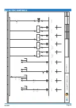
3.2 HYDRAULIC DIAGRAM
5
6
1
Sequence valve (adjustable)
2
Non-return valve
3
Flow-control valve with orifice
4
Valve
5
Filter
6
Hydraulic pump with electric motor
3.3 ELECTRICAL CONTROL CABINET
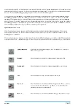
The electrical control boxes are used to operate the crowd gate. Push buttons are used to control the output for
the hydraulic unit and the electrical drive unit.
Two sensors prevent the crowd gate from moving too far on the rail tracks. These sensors are mounted on both
sides of the drive frame. When the crowd gate approaches the start or end positions, the sensor receives a signal to
stop.
Two sensors are positioned on the center frame to prevent the cows from getting squeezed when the crowd gate
moves towards the milking parlor. These sensors are positioned so that they receive a signal if the cylinders are in
or out. This confirms that the fence of the crowd gate is moved downwards. If one of the cows lies down in front
of the crowd gate, the fence is forced upwards. This means that the cylinders are extended and the signal from the
sensor is interrupted. If the signal is interrupted, the crowd gate stops moving towards the milking parlor.
Содержание Xcalibur
Страница 31: ...Page 31 9e1048 8 24 CONTROL BOX Relay Power Supply c...
Страница 32: ...Page 32 9e1048...
Страница 33: ......

