5 |
P a g e
Slot the next two motors into their mounts and place the four wires in terminal C3 tightening
the terminals when finished.
Connect THR and STR to your radio transmitter of choice, as shown.
Note: It will not damage
the electronics if you flip them but it will reverse driving and turning controls.
3.6
S
TEP
7
‐
A
SSEMBLE THE ROBOT
:
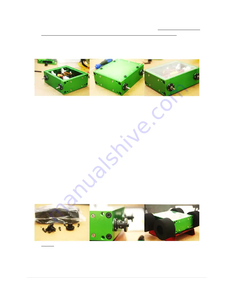
Carefully attach all of the plates as the end of construction draws near.
Slide the other side plate back onto the chassis.
Snug the bottom screws
Add the upper set of 10‐24 machine screws, then tighten the upper screws. This will result in the
lower screws becoming tight, as we achieve a compression fit around the motor gearbox. Hint:
While evenly tightening the 10‐24 x ¾ screws, look closely at the air gap between the side plates
and end plates. Tighten the screws in small increments to keep the air gaps even. Even air gaps
equal a squarely assembled, strong robot.
Attach the lower plate, using 8 of the supplied M3 machine screws.
Use blue Loctite to keep
these screws from coming loose during combat!
Lightly place the clear upper plate on the chassis and gently attach it with the 4 M3 screws.
Lightly attaching it is important because you will want to access the electronics a little later.
If you will be fighting in an arena with a steel floor, we offer optional magnets that can be
attached to the bottom of the robot to increase traction.
3.7
S
TEP
8
‐
A
TTACH
W
HEELS
:
Attach axle adapters on the axles and mount the wheels.
Loosely screw the supplied 4‐40 machine screws into the black aluminum axle adapters.
Slide each axle adapter fully onto a motor shaft, with the clamp portion towards the chassis, and
tighten the 4‐40 machine screws to secure the adapters to the motor shafts.
Slide a wheel onto each of the axle adapters, and secure with the supplied 6‐32 machine screws.
Your 4‐40 sized Allen wrench can be used to help align the holes in the wheel hub with the
tapped holes in the axle adapters.


