background image


46

5.


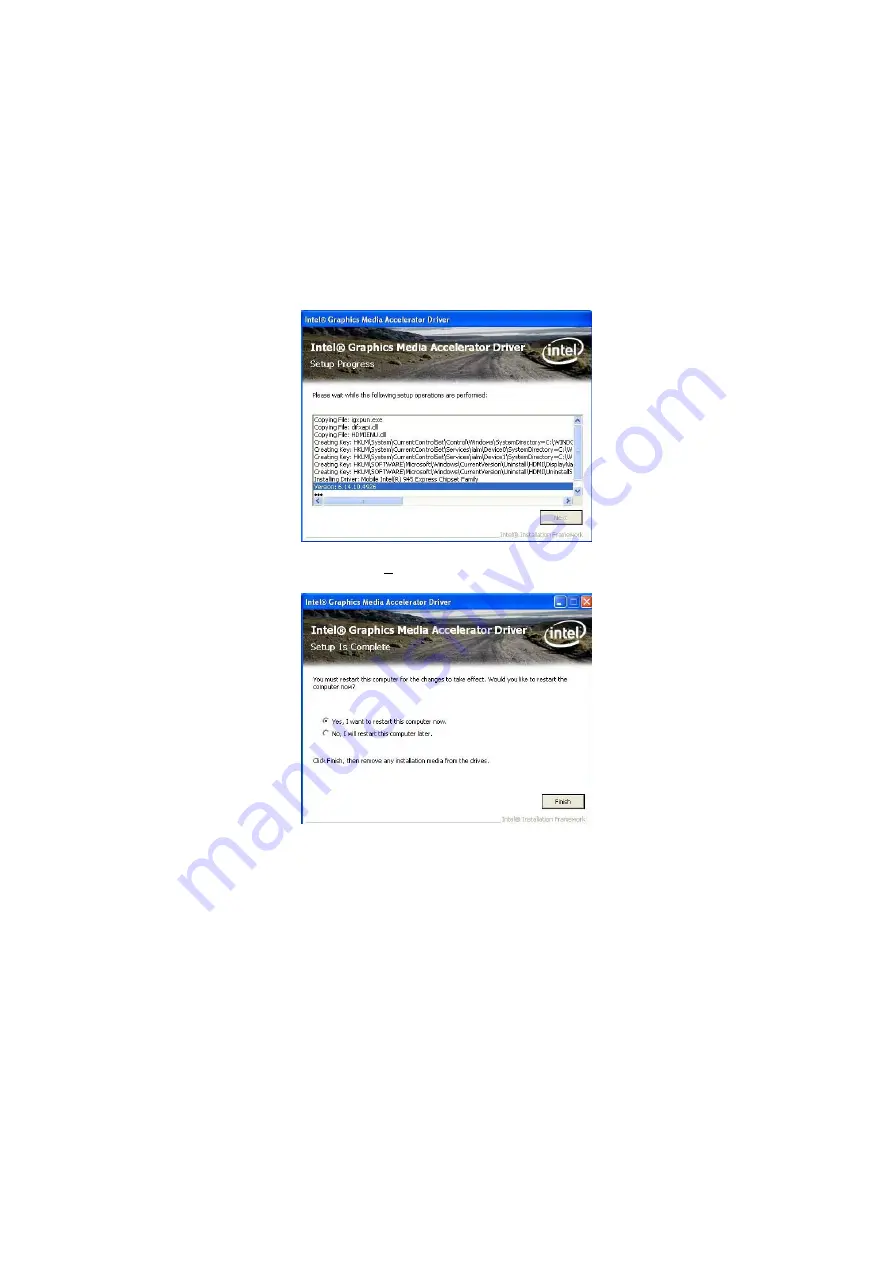
When 

Setup Progress

 finished, just click on 

Next

 button to 

proceed. 


6.


Please select 

“Yes, I want to restart my computer now”


button then click 

“Finish” 

to reboot your system to take the 

effect once the installation is completed. 


Содержание HS-7280

Страница 1: ...HS 7280 Intel Atom N270 processor PCI ISA Bus Single Board Computer CompactFlash DVI I CRT LVDS Dual Gigabit Ethernet Audio GPIO SATA RS 232 422 485 4 COM 4 USB2 0 WDT H W Monitor...

Страница 2: ...granted permission by BOSER Technology Co Ltd BOSER Technology Co Ltd reserves the right to change or improve the contents of this document without due notice BOSER Technology Co Ltd assumes no respon...

Страница 3: ...ctor List 9 3 5 Configuring the CPU 9 3 6 System Memory 9 3 7 VGA Controller 10 3 8 IDE Drive Connector 12 3 9 Serial ATA Connector 13 3 10 Serial Port Connectors 13 3 11 Ethernet Connector 14 3 12 US...

Страница 4: ...1 4 6 Advanced Chipset Features 32 4 7 Integrated Peripherals 34 4 8 Power Management Setup 37 4 9 PnP PCI Configurations 38 4 10 PC Health Status 39 4 11 Frequency Voltage Control 39 Chapter 5 Softwa...

Страница 5: ...mpleted on a sample of the equipment identified below Equipment Class Information Technology Equipment Product Model Series HS 7280 This Product Complies With EN55022 Class A for Radiated emissions EN...

Страница 6: ...strap available from most electronic component stores when handling boards and components Fasten the ALLIGATOR clip of the strap to the end of the shielded wire lead from a grounded object Please wear...

Страница 7: ...e board Additional features include an enhanced I O with CF CRT DVI I LVDS dual Gigabit Ethernet audio SATA 4 COM and 4 USB2 0 interfaces The Intel 945GSE integrated Intel GMA950 with 244MB shared mai...

Страница 8: ...CPU or generate an interrupt to resolve such condition 1 1 Major Features The HS 7280 comes with the following features Intel Atom N270 processor 1 6GHz 1 x DIMM up to 2GB DDR2 SDRAM Intel 945GSE ICH...

Страница 9: ...degrees C Operating Humidity 0 95 non condensing Board Size L x W 186 x 122 mm z I O Interface I O Port 3 x RS 232 1 x RS 232 422 485 6 x USB2 0 2 x external 1 x IDE 2 x SATA 1 x Parallel 1 x PS 2 fo...

Страница 10: ...4 z Ethernet Chipset Dual RealTek RTL8111C Gigabit Ethernet Ethernet Interface 2 x RJ 45 1 3 Board Dimensions...

Страница 11: ...a raised surface and carefully inspect the board for any damage that might have occurred during shipment Ground the board and exercise extreme care to prevent damage to the board from static electric...

Страница 12: ...ackage intact and store them in a safe dry place for any unforeseen event requiring the return shipment of the product In case you discover any missing and or damaged items from the list of items plea...

Страница 13: ...reminders and steps to take before you begin with your installation process 1 Make sure that all jumper settings match their default settings and CMOS setup correctly Refer to the sections on this cha...

Страница 14: ...nel Voltage Select 3 3V Short 2 3 10 JP6 CF Use Master Slave Select Slave Open 22 JP7 COM2 Use RS 232 or RS 422 485 Select RS 232 Open 13 JP8 AT ATX Power Mode Select ATX Open 16 JP9 Clear CMOS Normal...

Страница 15: ...nector 21 CN17 PS 2 6 pin Mini DIN KB MS Connector 17 CN18 15 pin CRT Connector 10 CN19 DVI I Connector 10 CN20 Internal 6 pin KB MS Connector 17 CN21 CN22 External USB2 0 Port 15 FN1 CPU Fan Power Co...

Страница 16: ...D 6 GND 7 GND 8 GND 9 N C 10 GND 11 N C 12 SDA 13 HSYNC 14 VSYNC 15 SDC 1 7 12 3 9 14 5 6 11 2 8 13 4 10 15 z JP3 JP2 LVDS Interface Connector PIN Description PIN Description 1 2 13 14 1 VLCD 2 VLCD 3...

Страница 17: ...the working voltage of the flat panel connected to the system Jumper JP1 offers two voltage settings for the user z JP1 Panel Voltage Select Options Settings 1 3 3 3V default Short 2 3 5V Short 1 2 z...

Страница 18: ...1 Reset 2 GND 3 DATA7 4 DATA 8 5 DATA 6 6 DATA 9 7 DATA 5 8 DATA 10 9 DATA 4 10 DATA 11 11 DATA 3 12 DATA 12 13 DATA 2 14 DATA 13 15 DATA 1 16 DATA 14 17 DATA 0 18 DATA 15 19 GND 20 N C 21 PDREQ 22 G...

Страница 19: ...Serial Port Connectors The HS 7280 offers 16C550 compatible UARTs with 16 byte Send Receive FIFO serial ports z JP4 JP5 JP12 JP11 COM1 COM4 Connector 5x2 header PIN Description PIN Description 1 9 10...

Страница 20: ...function 4 wires point to point full duplex RS 422 485 Typical RS 485 2 wires Mutildrop Network 3 11 Ethernet Connector The HS 7280 provides two RJ 45 connectors for 10 100 1000 Based LAN Please refer...

Страница 21: ...CN11 CN12 Internal USB2 0 Connector PIN Description PIN Description 1 2 7 8 1 VCC 2 VCC 3 USBD2 4 4 USBD3 5 5 USBD2 4 6 USBD3 5 7 GND 8 GND z CN21 CN22 External USB2 0 Connector PIN Description 1 VCC...

Страница 22: ...nector z CNN1 5 pin ATX Power Connector PIN Description 5 1 1 GND 2 PS_ON 3 12V 4 5VSB 5 VCC z JP8 AT ATX Power Mode Select Options Settings 2 1 ATX Mode default Open AT Mode Short z FN1 CPU Fan Power...

Страница 23: ...KB MS connector for HS 7280 z CN20 6 pin Keyboard Mouse Connector PIN Description 1 6 1 Keyboard Data 2 Mouse Data 3 GND 4 VCC 5 Keyboard Clock 6 Mouse Clock z CN17 PS 2 6 pin Mini DIN Keyboard Mouse...

Страница 24: ...izes for chassis front cover z CN2 System Front Panel Control PIN Description PIN Description 1 330 pull VCC 2 Speaker 3 HDD LED 4 N C 5 ATX Power Button 6 VCC 7 GND 8 330 pull VCC 9 Reset Switch 10 V...

Страница 25: ...setting value This function Watchdog Timer prevents user s software from crashing W83627EHG Watch Dog Timer 1 Assembly sample code Extended function mode MOV DX 2EH MOV AL 87H OUT DX AL OUT DX AL Con...

Страница 26: ...e 08H for minute mode OUT DX AL Configure reset time interval MOV DX 2EH MOV AL F6H OUT DX AL MOV DX 2FH MOV AL 05H Setup reset time 5 User can setup from 1 255 1H FFH OUT DX AL 2 DOS Debug Command o...

Страница 27: ...ct LN 5 Data 3 18 GND 6 Data 4 19 GND 7 Data 5 20 GND 8 Data 6 21 GND 9 Data 7 22 GND 10 Acknowledge 23 GND 11 Busy 24 GND 12 Paper Empty 25 GND 13 Printer Select 26 GND 13 1 26 14 3 19 Audio Connecto...

Страница 28: ...t Slave default Open z CN6 CompactFlash Socket PIN Description PIN Description 1 GND 2 DATA3 3 DATA4 4 DATA5 5 DATA6 6 DATA7 7 SDCS1 8 GND 9 GND 10 GND 11 GND 12 GND 13 VCC 14 GND 15 GND 16 GND 17 GND...

Страница 29: ...6 GD5 7 GD2 8 GD6 9 GD3 10 GD7 W83627EHG Digital I O 1 Assembly sample code Extended function mode MOV DX 2EH MOV AL 87H OUT DX AL OUT DX AL Configure logical device MOV DX 2EH MOV AL 07H OUT DX AL MO...

Страница 30: ...ut MOV DX 2EH MOV AL FOH OUT DX AL MOV DX 2FH MOV AL FEH Setup GPIO bit 0 as output Note1 OUT DX AL Note 1 Example Output Bit Instruction Bit 0 MOV AL FE Bit 1 MOV AL FD Bit 2 MOV AL FB Bit 3 MOV AL F...

Страница 31: ...25 2 DOS Debug Command o 2e 87 o 2e 87 o 2e 07 o 2f 07 o 2e 29 o 2f 01 o 2e 30 o 2f 01 o 2e f3 o 2f 00 o 2e f0 o 2f fe...

Страница 32: ...S 7280 can installed on BOSER backplanes like HPS 8SB v1 2 to support PCI to PCI Bridge AD selection for the environment of more PCI card z JP2 PCI PCI Bridge Enabled Disabled Select only for Backplan...

Страница 33: ...irst power on the computer The BIOS reads the system information contained in the CMOS and begins the process of checking out the system and configuring it When it finishes the BIOS will seek an opera...

Страница 34: ...m Move to previous item Esc key Main Menu Quit and not save changes into CMOS Status Page Setup Menu and Option Page Setup Menu Exit current page and return to Main Menu PgUp key Decrease the numeric...

Страница 35: ...S CMOS Setup Utility X Standard CMOS Features X Frequency Voltage Control X Advanced BIOS Features Load Fail Safe Defaults X Advanced Chipset Features Load Optimized Defaults X Integrated Peripherals...

Страница 36: ...Please use the IDE setup utility in BIOS setup to install the HDD correctly Phoenix AwardBIOS CMOS Setup Utility Standard CMOS Features Date mm dd yy Wed Jul 15 2009 Item Help Time hh mm ss 10 32 57 X...

Страница 37: ...e LS120 Boot Other Device Enabled Swap Floppy Drive Disabled Boot Up Floppy Seek Enabled Boot Up NumLock Status On Gate A20 Option Fast Typematic Rate Setting Disabled X Typematic Rate Chars Sec 6 X T...

Страница 38: ...ause they provide the best operating conditions for your system You must consider making any changes only if you discover that the data has been lost while using your system Phoenix AwardBIOS CMOS Set...

Страница 39: ...Single Channel Type 2 800 x 600 18 bit Single Channel Type 3 1024 x 768 18 bit Single Channel Type 4 1280 x 1024 18 bit Dual Channel Type 5 1440 x 1050 18 bit Dual Channel Type 6 1440 x 1050 18 bit D...

Страница 40: ...ard Serial Port 3 280 Serial Port 3 Use IRQ IRQ10 Onboard Serial Port 4 288 Serial Port 4 Use IRQ IRQ10 X USB Device Setting Press Enter Select Item PU PD Value F10 Save Esc Quit F1 General Help F5 Pr...

Страница 41: ...uto IDE Secondary Master UDMA Auto IDE Secondary Slave UDMA Auto On Chip Serial ATA Setting SATA Mode IDE On Chip Serial ATA Enhanced Mode SATA PORT Speed Settings Disabled X PATA IDE Mode Secondary S...

Страница 42: ...After PWR Fail Former Sts Select Item PU PD Value F10 Save Esc Quit F1 General Help F5 Previous Values F6 Fail Safe Defaults F7 Optimized Defaults Phoenix AwardBIOS CMOS Setup Utility USB Device Sett...

Страница 43: ...Down Disabled Soft Off by PWR BTTN Instant Off Wake Up by PCI card Enabled Power On by Ring Enabled Resume by Alarm Disabled X Date of Month Alarm 0 X Time hh mm ss Alarm 0 0 0 Reload Global Timer Ev...

Страница 44: ...hoenix AwardBIOS CMOS Setup Utility PnP PCI Configurations Init Display First PCI Slot Item Help Reset Configuration Data Disabled Resources Controlled By Auto ESCD X IRQ Resources Press Enter X DMA R...

Страница 45: ...Esc Quit F1 General Help F5 Previous Values F6 Fail Safe Defaults F7 Optimized Defaults 4 11 Frequency Voltage Control Phoenix AwardBIOS CMOS Setup Utility Frequency Voltage Control Auto Detect PCI C...

Страница 46: ...40 This page is the blank page...

Страница 47: ...ains an auto run program that invokes the installation programs for the chipset VGA LAN and audio drivers The following sections describe the installation procedures of each driver based on WinXP oper...

Страница 48: ...g the CHIPSET button in Step 1 the program launches the Setup that will assist you in the installation process Click on the Next button to proceed 3 The License Agreement dialog box then appears on th...

Страница 49: ...43 4 When the Readme File Information dialog box pops up just click on the Next button to proceed 5 Click on the Finish to completed the installation...

Страница 50: ...Driver Installation 1 Insert the CD that comes with the board into the CD ROM drive Click VGA to install video driver 2 The Welcome to the Setup program dialog box appears on the screen Choose Next t...

Страница 51: ...45 3 The Intel License Agreement dialog box appears on the screen Choose Yes to proceed 4 When the Readme File Information dialog box pops up just click on the Next button to proceed...

Страница 52: ...up Progress finished just click on Next button to proceed 6 Please select Yes I want to restart my computer now button then click Finish to reboot your system to take the effect once the installation...

Страница 53: ...ion 1 Insert the CD that comes with the board into the CD ROM drive Click LAN to install LAN driver 2 When the dialog box below appears make sure you close all other Windows applications the click on...

Страница 54: ...48 3 The Setup Status dialog box then appears on the screen 4 When setup is finished please reboot your computer to take the effect...

Страница 55: ...49 5 4 Audio Driver Installation 1 Insert the CD that comes with the board into the CD ROM drive Click Audio to install audio driver 2 When the dialog box below appears click on Yes to proceed...

Страница 56: ...50 3 Please select Yes I want to restart my computer now button then click Finish to reboot your system to take the effect once the installation is completed...

Отзывы: