background image


63

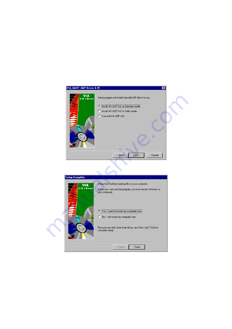
9.  The following screen then gives you the choice of installing the 

AGP driver in standard o turbo mode. Select on the Standard 

Mode and then click on Next to proceed. 


10.  Installation of the AGP driver is now complete. Once the screen 

below appears, select on restarting your computer to activate all 

drivers/settings completed. 


Содержание HS-6050

Страница 1: ...70 133MHz FSB PICMG Bus Industrial Single Board Computer Full Size All in One CRT 133MHz FSB ATA 33 66 100 Dual LAN Audio RS 232 422 485 PC 104 IrDA USB DOC WDT H W Monitor PICMG Bus Industrial Single...

Страница 2: ...ed permission by BOSER Technology Co Ltd BOSER Technology Co Ltd reserves the right to change or improve the contents of this document without due notice BOSER Technology Co Ltd assumes no responsibil...

Страница 3: ...ess Setting 10 3 8 VGA Controller 12 3 9 PCI E IDE Drive Connector 13 3 10 Floppy Disk Drive Connector 14 3 11 Serial Port Connectors 15 3 12 Parallel Connector 16 3 13 Ethernet Connector 17 3 14 IrDA...

Страница 4: ...etup 44 4 3 Main Menu 45 4 4 Standard CMOS Features 46 4 5 Advanced BIOS Features 47 4 6 Advanced Chipset Features 48 4 7 Integrated Peripherals 49 4 8 Power Management Setup 50 4 9 PnP PCI Configurat...

Страница 5: ...strap available from most electronic component stores when handling boards and components Fasten the ALLIGATOR clip of the strap to the end of the shielded wire lead from a grounded object Please wear...

Страница 6: ...This Page is intentionally left blank...

Страница 7: ...allows the HS 6050 to support data transfers of 33 66 or 100MB sec to each IDE drive connection Designed with the VIA VT8601 core logic chipset the board supports Intel Celeron Coppermine Tualatin an...

Страница 8: ...the onboard Watchdog Timer WDT will automatically reset the CPU or generate an interrupt to resolve such condition 1 1 Major Features The HS 6050 comes with the following features Socket 370 for Inte...

Страница 9: ...PP LAN Dual RealTek RTL8100 10 100 Based LAN Audio AC97 3D audio controller supporting speaker out Serial Port 16C550 UART compatible RS 232 422 485 x 1 and RS 232 x 1 serial ports with 16 byte FIFO P...

Страница 10: ...4 1 3 Board Dimensions...

Страница 11: ...age to the board from static electricity Integrated circuits will sometimes come out of their sockets during shipment Examine all integrated circuits particularly the BIOS processor memory modules ROM...

Страница 12: ...the delivery package intact and store them in a safe dry place for any unforeseen event requiring the return shipment of the product In case you discover any missing and or damaged items from the lis...

Страница 13: ...ur installation process 1 Make sure that all jumper settings match their default settings and CMOS setup correctly Refer to the sections on this chapter for the default settings of each jumper 2 Go th...

Страница 14: ...8 3 2 Board Layout...

Страница 15: ...r List Connector Definition CN1 5 pin Keyboard Connector CN2 Front Panel Signal Connector CN3 IrDA Connector CN4 ATX Power Connector CN5 5 pin ATX Power Controller CN6 Primary IDE Connector CN7 Second...

Страница 16: ...he onboard memory is 1 5GB 3 7 DiskOnChip Address Setting The DiskOnChip function allows the system to boot or operate without a FDD or a HDD DiskOnChip modules may be formatted as drive C or A With D...

Страница 17: ...t Pin 1 can be found on the lower right corner of the chip Please refer to the diagram for the exact location 3 Once you have figured out where the pin 1 locations are on both chip and socket align th...

Страница 18: ...so might damage the pins in the process 3 Slowly lift the screwdriver handle upwards This will disengage the module from its socket NOTE If you encounter difficulty removing your DiskOnChip module pl...

Страница 19: ...N7 CN6 CN7 Primary Secondary IDE Connector PIN Description PIN Description 1 RESET 2 GND 3 DATA 7 4 DATA 8 5 DATA 6 6 DATA 9 7 DATA 5 8 DATA 10 9 DATA 4 10 DATA 11 11 DATA 3 12 DATA 12 13 DATA 2 14 DA...

Страница 20: ...d to CN12 at any given time CN12 FDD Connector PIN Description PIN Description 1 GND 2 RWC 3 GND 4 N C 5 GND 6 DS1 7 GND 8 Index 9 GND 10 Motor Enable A 11 GND 12 Drive Select B 13 GND 14 Drive Select...

Страница 21: ...e RS 232 or RS 422 485 function CN11 CN13 COM1 COM2 Connectors 5x2 Header PIN Description PIN Description 1 DCD 2 DSR 3 RXD 4 RTX 5 TXD 6 CTX 7 DTR 8 RI 9 GND 10 N C 2 4 6 8 10 1 3 5 7 9 DSR RTX CTX N...

Страница 22: ...2 485 Selection Serial Port Setting JP6 JP7 RS 232 Short 3 5 4 6 Short 3 5 4 6 RS 422 485 Short 1 3 2 4 Short 1 3 2 4 3 12 Parallel Connector CN17 is a standard 26 pin flat cable connector deigned to...

Страница 23: ...C GND 5 1RC GND 6 1RX 7 1RC GND 8 1RC GND 9 2TX 10 2TX 11 2RX 12 2RC GND 13 2RC GND 14 2RX 15 2RC GND 16 2RC GND CN19 CN20 Internal LAN1 and LAN2 Connector PIN Description PIN Description 1 VCC3 2 LIN...

Страница 24: ...umper on JP1 JP1 Clear CMOS Options Settings Normal Operation Short 1 2 Clear CMOS Short 2 3 IMPORTANT The default setting of JP1 is Short 1 2 Before you turn on the power of your system please check...

Страница 25: ...connectors FN1 FN2 Fan1 Fan2 Connectors PIN Description 1 Fan Speed 2 12V 3 GND 3 19 Keyboard Connectors The HS 6050 offers two possibilities for keyboard connections The connections are via CN26 for...

Страница 26: ...nector The HS 6050 offers two possibilities for keyboard connections The connections are via CN24 for an external PS 2 type keyboard or via CN21 for an internal 4 pin connector CN24 PS 2 6 pin Mini Di...

Страница 27: ...e access cycles of Watchdog Timer The Enable cycle proceeds via READ PORT 443H whereas the Disable cycle proceeds via READ PORT 045H A continued Enable cycle after a first Enable cycle means Refresh O...

Страница 28: ...esh cycle and reading the control port 443H or via a Disable cycle and reading the disable control port 045H After an Enable cycle of WDT user must immediately execute a Refresh cycle to WDT before it...

Страница 29: ...5H WT_Enable PUSH AX keep AX DX PUSH DX MOV DX WDT_EN_RF enable the WDT IN AL DX POP DX get back AX DX POP AX RET WT_Refresh PUSH AX keep AX DX PUSH DX MOV DX WDT_ET_RF refresh the WDT IN AL DX POP DX...

Страница 30: ...les NOTE The PC 104 connector allows direct plugging or stack through piling of PC 104 modules without requiring the PC 104 mounting kit CN16 40 pin PC 104 Expansion Slot PIN Description PIN Descripti...

Страница 31: ...EN 43 SMEMW 12 SA19 44 SMEMR 13 SA18 45 IOW 14 SA17 46 IOR 15 SA16 47 DACK3 16 SA15 48 DRQ3 17 SA14 49 DACK1 18 SA13 50 DRQ1 19 SA12 51 REFRESH 20 SA11 52 SYSCLK 21 SA10 53 IRQ7 22 SA9 54 IRQ6 23 SA8...

Страница 32: ...e Out port supports a preamp function that allows user to connect either a passive set of speakers or earphones JP8 Line Out Connector PIN Description PIN Description 1 AOUTL 2 AOUTR 3 GND 4 GND 5 MIC...

Страница 33: ...of the disks and then launch and turn control over to the operating system While the BIOS is in control the Setup program can be activated in one of two ways 1 By pressing Del immediately after switc...

Страница 34: ...meric value or make changes key Increase the numeric value or make changes key Decrease the numeric value or make changes F1 key General help only for Status Page Setup Menu and Option Page Setup Menu...

Страница 35: ...ights Reserved Standard CMOS Setup Advanced CMOS Setup Advanced Chipset Setup Power Management Setup PCI Plug and Play Setup Peripheral Setup Hardware Monitor Setup Auto Detect Hard Disks Change User...

Страница 36: ...etup Utility in BIOS SETUP to install the HDD correctly AMIBIOS SETUP STANDARD CMOS SETUP C 2001 American Megatrends Inc All Rights Reserved Date mm dd yyyy Thu Jan 03 2002 Base Memory 0 KB Time hh mm...

Страница 37: ...nabled 3rd Boot Device CD ROM Try Other Boot Devices Yes S M A R T for Hard Disks Disabled BootUp Num Lock On Floppy Drive Swap Disabled Floppy Drive Seek Disabled PS 2 Mouse Support Enabled Primary D...

Страница 38: ...y if you discover that the data has been lost while using your system AMIBIOS SETUP ADVANCED CHIPSET SETUP C 2001 American Megatrends Inc All Rights Reserved DRAM Timing Available Options Configure SD...

Страница 39: ...andby Time Out Minute Disabled Suspend Time Out Minute Disabled Throttle Slow Clock Ratio 50 56 25 Display Activity Ignore IRQ3 Ignore IRQ4 Ignore IRQ5 Monitor IRQ7 Ignore IRQ9 Ignore IRQ10 Monitor IR...

Страница 40: ...AND PLAY SETUP C 2001 American Megatrends Inc All Rights Reserved Plug and Play Aware O S No Available Options Clear NVRAM Yes No OnChip VGA Frame Buffer Size None PCT Latency Timer PCI Clocks 32 Yes...

Страница 41: ...d then let the controller and the CPU perform the complete task by them This is much simpler and more efficient also faster AMIBIOS SETUP PERIPHERAL SETUP C 2001 American Megatrends Inc All Rights Res...

Страница 42: ...Megatrends Inc All Rights Reserved System Hardware Monitor Available Options Chassis Intrusion Disabled Disabled TSENS1 Temperature Enabled TSENS2 Temperature Reset CPU Fan Speed Chassis Fan Speed Vc...

Страница 43: ...ppear listed beside the drive letter on the screen AMIBIOS HIFLEX SETUP UTILITY VERSION 1 54 C 2001 American Megatrends Inc All Rights Reserved Standard CMOS Setup Advanced CMOS Setup Advanced Chipset...

Страница 44: ...and change the options of the setup menus user password just can only enter but do not have the right to change the options of the setup menus When you select this function the following message will...

Страница 45: ...trying to enter Setup 4 13 Auto Configuration with Optimal Settings When you press Enter on this item you will get a confirmation dialog box with a message shown below This option allows you to load...

Страница 46: ...alues that are factory settings for optimal performance system operations AMIBIOS HIFLEX SETUP UTILITY VERSION 1 54 C 2001 American Megatrends Inc All Rights Reserved Standard CMOS Setup Advanced CMOS...

Страница 47: ...Configuration with Optimal Settings Auto Configuration with Fail Safe Settings Save Settings and Exit Exit Without Saving Standard CMOS setup for changing time date hard disk type etc ESC Exit Sel F2...

Страница 48: ...LEX SETUP UTILITY VERSION 1 54 C 2001 American Megatrends Inc All Rights Reserved Standard CMOS Setup Advanced CMOS Setup Advanced Chipset Setup Power Management Setup Quit without saving Y N N Change...

Страница 49: ...stem on one of the disks and then launch and turn control over to the operating system While the BIOS is in control the Setup program can be activated in one of two ways 1 By pressing Del immediately...

Страница 50: ...meric value or make changes key Increase the numeric value or make changes key Decrease the numeric value or make changes F1 key General help only for Status Page Setup Menu and Option Page Setup Menu...

Страница 51: ...y Copyright 1984 2001 Award Software Standard CMOS Features Advanced BIOS Features Advanced Chipset Features Integrated Peripherals Power Management Setup PnP PCI Configurations PC Health Status Frequ...

Страница 52: ...install the HDD correctly CMOS Setup Utility Copyright 1984 2001 Award Software Standard CMOS Features Date mm dd yy Wed Jul 11 2001 Item Help Time hh mm ss 10 32 57 Menu Level X X IDE Primary Master...

Страница 53: ...Enabled year and century First Boot Device Floppy Second Boot Device HDD 0 Third Boot Device CD ROM Boot Other Device Enabled Swap Floppy Drive Disabled Boot Up Floppy Seek Enabled Boot Up Num Lock St...

Страница 54: ...ight 1984 2001 Award Software Advanced Chipset Features DRAM Clock Host Clock Item Help DRAM Timing by SPD Enabled Menu Level X SDRAM Cycle Length 3 Bank Interleave Disabled Memory Hole at 15M 16M Dis...

Страница 55: ...el 0 Auto Item Help On chip IDE Channel 1 Auto Menu Level X IDE Prefetch Mode Enabled IDE Primary Master PIO Auto IDE Primary Slave PIO Auto Change the day month IDE Second Master PIO Auto year and ce...

Страница 56: ...nd Type S1 PM Control by APM Yes Video Off Option Suspend Off Modem use IRQ 3 Soft off by PWRBTN Delay 4Sec Wake Up Event VGA VGA LPT COM LPT COM HDD FDD On PCI Master Off Modem Ring Resume Disabled R...

Страница 57: ...Level X Resources controlled By Auto ESCD IRQ Resources IRQ3 Assign PCI ISA PNP Change the day month IRQ4 Assign PCI ISA PNP year and century IRQ5 Assign PCI ISA PNP IRQ6 Assign PCI ISA PNP IRQ7 Assig...

Страница 58: ...nt CPU Temp Item Help Current System Temp Menu Level X Current CPUFAN1 Speed Current CPUFAN2 Speed Change the day month year and century Vcore 3 3V 5V 12V 12V Shutdown Temperature Select Item PU PD Va...

Страница 59: ...most stable minimal performance system operations CMOS Setup Utility Copyright 1984 2001 Award Software X STANDARD CMOS Features X Frequency Voltage Control X Advanced BIOS Features Load Fail Safe De...

Страница 60: ...fault values that are factory settings for optimal performance system operations CMOS Setup Utility Copyright 1984 2001 Award Software X Standard CMOS Features X Frequency Voltage Control X Advanced B...

Страница 61: ...he options of the setup menus user password just can only enter but do not have the right to change the options of the setup menus When you select this function the following message will appear at th...

Страница 62: ...ccurs when trying to enter Setup 4 14 Save Exit Setup Pressing Enter on this item asks for confirmation Pressing Y stores the selections made in the menus in CMOS a special section of memory that stay...

Страница 63: ...d restarts your computer CMOS Setup Utility Copyright 1984 2001 Award Software X Standard CMOS Features X Frequency Voltage Control X Advanced BIOS Features Load Fail Safe Defaults X Advanced Chipset...

Страница 64: ...58 This page is intentionally left blank...

Страница 65: ...stallation The utility disk that came with the delivery package contains an auto run program that invokes the installation programs for the IDE VGA and Audio drivers The following describes the instal...

Страница 66: ...pears on the screen make sure to close any applications running and then click on the Next button 4 When the Readme window pops on the screen you may read the whole document including the license agre...

Страница 67: ...d Select on Normally Install and then click on Next 6 The next window lists all components detected in your system and asks you to select the ones requiring drivers Tick on all items then proceed by c...

Страница 68: ...API driver when you click the Next button on the screen below 8 When the ATAPI driver is completely installed The utility then displays your DMA mode status and allows you to enable it Tick on the box...

Страница 69: ...ng the AGP driver in standard o turbo mode Select on the Standard Mode and then click on Next to proceed 10 Installation of the AGP driver is now complete Once the screen below appears select on resta...

Страница 70: ...then select the CD ROM drive As soon as the system reads the disk the following screen will appear on your display Click on VIA_IDE from the main menu to start installing the VIA ID Tool 2 Once the We...

Страница 71: ...ents dialog box is now displayed Select on Install and then click on Next 4 Choose the folder to where the program will install the driver Select the default folder C Program Files IDETOOL and then cl...

Страница 72: ...continue with the installation 6 The program now installs and transfers the files to your system After it finishes you will be prompted to restart your system We recommend you to reboot your computer...

Страница 73: ...Windows screen it will display a new icon along the right hand task bar This icon represents the IDE Tool quick launch program 8 Double clicking on this new task bar icon will launch the IDE Tool s Dr...

Страница 74: ...stem When you select any hardware the right column displays the device s information and specifications You may also update the settings of your devices from the right column 10 Once you select the ID...

Страница 75: ...le Manager and then select the CD ROM drive As soon as the system reads the disk the VGA Menu screen below will appear on your display Click on VIA_AC97 from the main menu 2 Once the Welcome screen ap...

Страница 76: ...omponents dialog box is now displayed Select on Install driver and then click on Next 4 The program will now require the Windows installation disk for proper hardware installation Insert the CD and th...

Страница 77: ...n your screen Setup is already installing and copying the related files onto your hard drive Click on the Next button to proceed 6 After the audio driver installation finishes select the Finish button...

Страница 78: ...Disk still in your CD ROM drive right click on My Computer icon from the Windows menu Select on System Properties and then proceed to the Device Manager from the main menu 2 Select on Other Devices f...

Страница 79: ...73 3 The PCI Ethernet Controller Properties screen then appears allowing you to re install the driver Select Driver from the main menu to proceed...

Страница 80: ...inue 5 The program will then launch the Update Device Driver Wizard window that will install your device driver Click on the Next button to proceed to the next step 6 When the succeeding window asks y...

Страница 81: ...fy by ticking the path of the new driver Tick on the open boxes where you require the program to search for the device driver then click on the Browse button to manually specify the path 8 Press on th...

Страница 82: ...ion will appear Press on the Next button to continue 10 Once the program detects the device driver inf file from your specified location it will automatically copy the files into your hard drive 11 Wh...

Страница 83: ...ess Once the driver is completely installed the following message appears on your display Click on the Finish button to proceed 13 Restart your computer to make the new system settings take effect Cli...

Страница 84: ...h the Utility CD Disk still in your CD ROM drive right click on Network Neighborhood icon from the Windows menu Select on Properties 2 The system automatically detects the absence of Windows NT Networ...

Страница 85: ...79 3 Tick on the Wired to Network once the following screen appears Click on the Next to proceed 4 Click on the Start Search button for the program to locate the Network Adapter...

Страница 86: ...list a number of adapters for you to choose from Press on the Have Disk button to assign the driver path location 6 Setup now asks you for the location of the driver When you have entered the new dri...

Страница 87: ...ds about the new driver it will display the device it found on the following screen Press on the OK button to accept and proceed 8 Setup then returns to Network Setup Wizard screen and displays your n...

Страница 88: ...lect the appropriate protocol and then click on Next to continue 10 Before Setup starts installing the components found and the settings you made it will give you the option to proceed or go back for...

Страница 89: ...s necessary to update the system information Specify the path then press Continue 12 Once it finishes copying the files Setup will now allow you to choose the Duplex Mode of your LAN controller Press...

Страница 90: ...84 13 When Setup asks if you wish to change the TCP IP settings of your system select the appropriately The default choice is No 14 Setup then starts the Networking installation and copies the files...

Страница 91: ...shes copying the TCP IP properties of your system will then pop up on your screen like the one shown below Make the necessary changes then click on OK to continue 16 When the screen below appears clic...

Страница 92: ...then prompts you that it is ready to start the network You may complete the installation thereafter Click on Next to continue 18 Assign the workgroup or domain setting of your computer Click on Next...

Страница 93: ...87 19 Restart your computer once the screen below appears Click on Finish to continue 20 Click on the Yes button to restart your computer The LAN driver installation for WIN NT4 0 is now complete...

Страница 94: ...88 This Page is intentionally left blank...

Отзывы: