background image


7

Chapter 3 

Hardware Installation 

This chapter illustrates how to install components into the compact PC 
system. Please refer to system board’s manual for the external 
interface. 

3.1 HDD 

Installation 

1. 

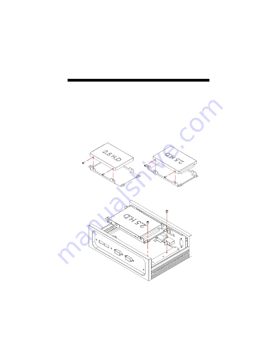
Follow the photo instructions to install the HDD onto the HDD 
mounting bracket. 


2. 

Follow the photo instructions to install the HDD_KIT onto the 
chassis. 

Содержание BBS-2004

Страница 1: ...BBS 2004 Fanless Box PC with VIA V4 Eden 1GHz or Atom N270 CF 12V DC In...

Страница 2: ...ranted permission by BOSER Technology Co Ltd BOSER Technology Co Ltd reserves the right to change or improve the contents of this document without due notice BOSER Technology Co Ltd assumes no respons...

Страница 3: ...ajor Features 2 1 2 Specifications 2 1 3 Dimensions 4 Chapter 2 Unpacking 5 2 1 Opening the Delivery Package 5 2 2 Inspection 5 Chapter 3 Hardware Installation 7 3 1 HDD Installation 7 3 2 Installatio...

Страница 4: ...mpleted on a sample of the equipment identified below Equipment Class Information Technology Equipment Product Model Series BBS 2004 This Product Complies With EN55022 Class A for Radiated emissions E...

Страница 5: ...anyway Do not insert objects into openings Do not immerse the product in water or permit liquids to spill inside of the product Turn off power when the product is unattended or not in use Unplug prod...

Страница 6: ...This page intentionally left blank...

Страница 7: ...board The BBS 2004 series provides VGA LAN MIC In Line Out COM USB2 0 and KB MS ports The BBS 2004 series is IBM PC AT compatible and can be drawn from a large body of hardware and software resources...

Страница 8: ...DD space Option for 12V DC in 60W adapter 1 2 Specifications Mechanical Dimensions LxHxW 19 0 x 5 8 x 13 6 cm Operation Storage Temperature 0 45 degrees C 20 70 degrees C EMC FCC CE Power In 12V DC in...

Страница 9: ...x LAN CF PS 2 KB MS VGA Rear I O 01 USB2 0 2 06 Main Power ON OFF 11 COM 2 02 COM 2 07 MIC In 12 KB MS 03 12V DC In or DC Adapter In 08 Line Out 13 VGA 04 Reset Button 09 LAN 2 14 USB2 0 05 USB2 0 2 1...

Страница 10: ...e time out intervasls from 1 255 sec or 1 255 min External I O 4 x USB2 0 4 x COM LAN PS 2 KB MS VGA MIC In Line Out Rear I O 01 USB2 0 2 05 USB2 0 2 09 KB MS 02 COM 2 06 Main Power ON OFF 10 VGA 03 1...

Страница 11: ...cise carefrlly to prevent any damage to the board from static Integrated circuits will sometimes come out of their sockets during shipment Examine all integrated circuits particularly the BIOS process...

Страница 12: ...6 This page intentionally left blank...

Страница 13: ...omponents into the compact PC system Please refer to system board s manual for the external interface 3 1 HDD Installation 1 Follow the photo instructions to install the HDD onto the HDD mounting brac...

Страница 14: ...8 3 2 Installation SBC 3 2 1 BBS 2004 G HS 2615 1 Install the SBC with chassis...

Страница 15: ...9 3 2 2 BBS 2004 I HS 2621 1 Install the SBC with chassis...

Страница 16: ...10 3 3 Cover Installation...

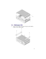
Страница 17: ...11 3 4 Wallmount Kit 1 There are two wallmount accessories coming with package Please use them shown below...

Страница 18: ...12 This page intentionally left blank...

Отзывы: