12
DISASSEMBLY/ASSEMBLY PROCEDURES
Note: The 3202 II loudspeaker has two Vee
Four driver assemblies. The cover does not
need to be removed to access the lower
driver assembly.
5. Vee Four Lower Driver Removal
5.1 Disconnect the two wires connected to
the terminals on the driver assembly.
5.2 Remove the four screws holding the
driver assembly to the cabinet.
5.3 Remove the driver assembly.
6. Vee Four Lower Driver Replacement
6.1 Place the new Vee Four driver assem-
bly onto the cabinet.
6.2 Secure driver assembly to the cabinet
using the screws provided in the new driver
assembly packaging.
6.3 Perform the test procedures on page
13.
7. Crossover Component Removal
7.1 Perform steps 1.1 and 1.2.
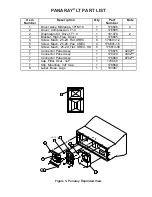
7.2 To remove the capacitors remove the
screws from the bracket (12) and discon-
nect the wires.
7.3 To remove the inductor assembly (13)
remove the screw (19) from the center of
the inductor. Disconnect the inductor from
the capacitor and the wire harness and
remove the inductor.
8. Crossover Component Replacement
8.1 Reconnect the wires to the new ca-
pacitor and place it into the cabinet. Place
the bracket (12) over the capacitor and
secure it to the cabinet.
8.3 Place the new inductor assembly (13)
into the cabinet and secure it to the cabinet.
Connect the wires to the capacitor and wire
harness.
8.4 Perform the test procedures on page
13.
8.5 Perform step and 2.5.
3202™/4402™/9702™ SERIES II


