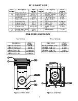
Bose 601 II DIRECT/REFLECTING Скачать руководство пользователя страница 7

6

601 II PART LIST

CROSSOVER COMPONENTS

Two Terminal

Three Terminals

Description

Part

Number

Capacitor, 3.4uF, 5%

106825

Capacitor, 4.0uF, 5%

108980

Capacitor, 3.0uF, 5%

104130

Resistor, 3.9

, 15W

119094-3R9

Resistor, 3.0

, 15W

119094-3R0

Resistor, 5.1

, 15W

119094-5R1

Description

Part

Number

Tweeter protection Lamp

114462

Capacitor, 6.8uF, 5%

115136

Capacitor, 8.0uF, 5%

115137

Capacitor, 6.0uF, 5%

109430

Resistor, 1

, 15W, 5%

102778-1R0

Figure 2.  Front View

Figure 3.  Top View

Item

Number

Description

Part

Number

Item

Number

Description

Part

Number

1

Grille, Side Plastic

116927

11

Screw, F Tweeter

119095-22

1A

Screw, Hex Head

118065-12

12

Screw, R Tweeter

119094-14

2

Grille Assembly

115143-1

13

Port Trim Ring

117529-1

3

Nameplate

110009

14

Top Woofer Cup

122101

4

Screw, #8 x 30mm  

129027-16

15

Gasket, Woofer

Cup

117717

5

Tinnerman Clip

117718

16

Screw #8-32 x .872

114986-15

6

Gasket, Woofer

120715

17

Rubber Foot

112992

7

Woofer Trim Ring

117530

18

Screw, foot

123284-20

8 Woofer 8 Inch                181870-0

01

          19 Gasket, Woofer,

Top

118930

9

Rubber Insert, Grille

117995

-

Grille Fastener

117788

10

Tweeter, 3 Inch

130714

3

2

1 1A

4

9

17 18

6

7

8

4

7

8

16

14 15

1A

13

10 11 12 20

5

19

Содержание 601 II DIRECT/REFLECTING

Страница 1: ...601 II DIRECT REFLECTING SPEAKER SYSTEM Service Manual P N 118915 ...

Страница 2: ...01 II Ports 3 601 II Test Procedures 4 Disassembly Assembly Procedures 5 601 II Part List 6 Figure 2 Front View 6 Figure 3 Top View 6 Figure 4 Part 1 Left Three Terminal Schematic 7 Figure 5 Part 2 Right Three Terminal Schematic 7 Figure 6 Two Terminal Schematic 8 ...

Страница 3: ... tweeters per enclosure provide flat power radiation beyond 15KHz The response extends down to 1 5KHz for use with the Dual Fre quency crossover network Two tweeters in each speaker enclosure are directed outward so that most of the sound energy is reflected off the back and side walls One tweeter is posi tioned so that the sound energy is directed towards the center of the room and the final twee...

Страница 4: ...um 150 watts maximum Major Port Frequency 35HZ Subport Frequency Broad band tuning centered at 240HZ Dual Frequency Crossover Woofer transition frequency 2 5kHZ Tweeter transition frequency 1 5kHZ Shipping Weight 46 LB per speaker Speaker Weight 36 LB per speaker Speaker Dimensions 29 5 H X 14 W X 13 D Figure 1 601 II Ports Sub ports Main Ports ...

Страница 5: ...stinguish between normal suspension noise and rubs or ticks dis place the cone of the driver slightly with your fingers If the noise can be made to go away or get worse it is a rub or tick and the driver should be replaced If the noise stays the same it is normal suspension noise and it will not be heard with program mate rial 3 Air Leak Test 3 1 Apply a 10Vrms 40HZ signal to the input terminals o...

Страница 6: ...ring configura tion 4 Woofer Replacement 4 1 Strip the wires and connect them to the woofer Use the schematic diagrams on page 7and 8 to ensure proper wiring 4 2 Replace the four screws that secure the woofer and the dress ring to the cabi net Note The replacement woofer will come with a dress ring that is not glued to the woofer Remove the dress ring from the replacement woofer and discard it 5 T...

Страница 7: ...cription Part Number Item Number Description Part Number 1 Grille Side Plastic 116927 11 Screw F Tweeter 119095 22 1A Screw Hex Head 118065 12 12 Screw R Tweeter 119094 14 2 Grille Assembly 115143 1 13 Port Trim Ring 117529 1 3 Nameplate 110009 14 Top Woofer Cup 122101 4 Screw 8 x 30mm 129027 16 15 Gasket Woofer Cup 117717 5 Tinnerman Clip 117718 16 Screw 8 32 x 872 114986 15 6 Gasket Woofer 12071...

Страница 8: ...RONT TWEETER RIGHT FRONT TWEETER RIGHT REAR TWEETER C D C2 RT2 R2 R1 RT1 C1 A A B YL GY GY GY GY RD RD GN BK FRONT WOOFER TOP WOOFER LEFT REAR TWEETER LEFT FRONT TWEETER RIGHT FRONT TWEETER RIGHT REAR TWEETER C D GY Figure 4 Part 1 Left Three terminal Schematic Figure 5 Part 2 Right Three Terminal Schematic ...

Страница 9: ...8 C1 R1 TOP WOOFER FRONT WOOFER LEFT REAR TWEETER LEFT FRONT TWEETER RIGHT FRONT TWEETER RIGHT REAR TWEETER RD GY YL GN BK GY RD GY BK _ Figure 6 Two Terminal Schematic ...

Страница 10: ...9 ...

Страница 11: ...CIFICATIONS AND FEATURES SUBJECT TO CHANGE WITHOUT NOTICE Bose Corporation The Mountain Framingham Massachusetts USA 01701 P N 118915 3 96 Rev 3 FOR TECHNICAL ASSISTANCE OR PART ORDERS CALL 1 800 367 4008 ...

Отзывы: