6
6 720 606 692 (02.05)
4.4
Maintenance
When it has been in service for a year, the appliance
should be inspected, thoroughly cleaned and, if
necessary, descaled.
Servicing may only be carried out by an authorised person.
Before carrying out maintenance work of any kind, the gas
and cold water isolating cocks must be turned off.
Heat Exchanger body
Clean the flue side of the heat exchanger block. Check
heat exchanger body and connecting pipes for scale and if
necessary descale with proprietary descaler according to
manufacturers instructions.
The descaling is done only to the heat exchanger, the
chemicals used damage the HDG and other parts.
Test for leaks at max. 2000 kPa.
Use new gasket when re-assembling.
Burner
Unscrew burner and clean in soap solution if necessary.
Pilot burner
The flame should heat the flame-failure electrode (diagram
3, item 4). If the flame is too small, clean pilot burner.
Slow ignition valve
After unscrewing the valve, clean out any dirty particles.
The ball inside the valve must move freely (check by shaking).
Inspect the O-ring and replace if necessary. Screw the slow
ignition valve back in. Check all connections for leaks.
Checking the vacuum chamber
-
Push the sliding gas control to the right and draw off hot
water.
-
Disconnect green lead from the servo gas valve (diagram
3, item 1). The main burner should go out and the pilot
burner remains lit. Disconnect the red lead from the pilot
gas valve (diagram 3, item 3) - the pilot flame should
then go out.
-
Re-connect red lead, pilot burner should re-ignite.
-
Re-connect green lead, main burner should re-ignite.
Functional Test
(does not apply to first time commissioning).
Switch off appliance. When a hot water tap is turned on,
the burner should come on full within 5 seconds. When the
hot water tap is turned off, the burner should go out within
approximately 2 seconds.
Diagram 7
G661_009
G661_016
Diagram 6
4.3
Conversion to Other Gases
Only use conversion kits supplied by the manufacturer.
This operation must be carried out by a qualified fitter.
1. Cut off the gas supply by closing the gas isolating valve,
and remove the front cover of the appliance;
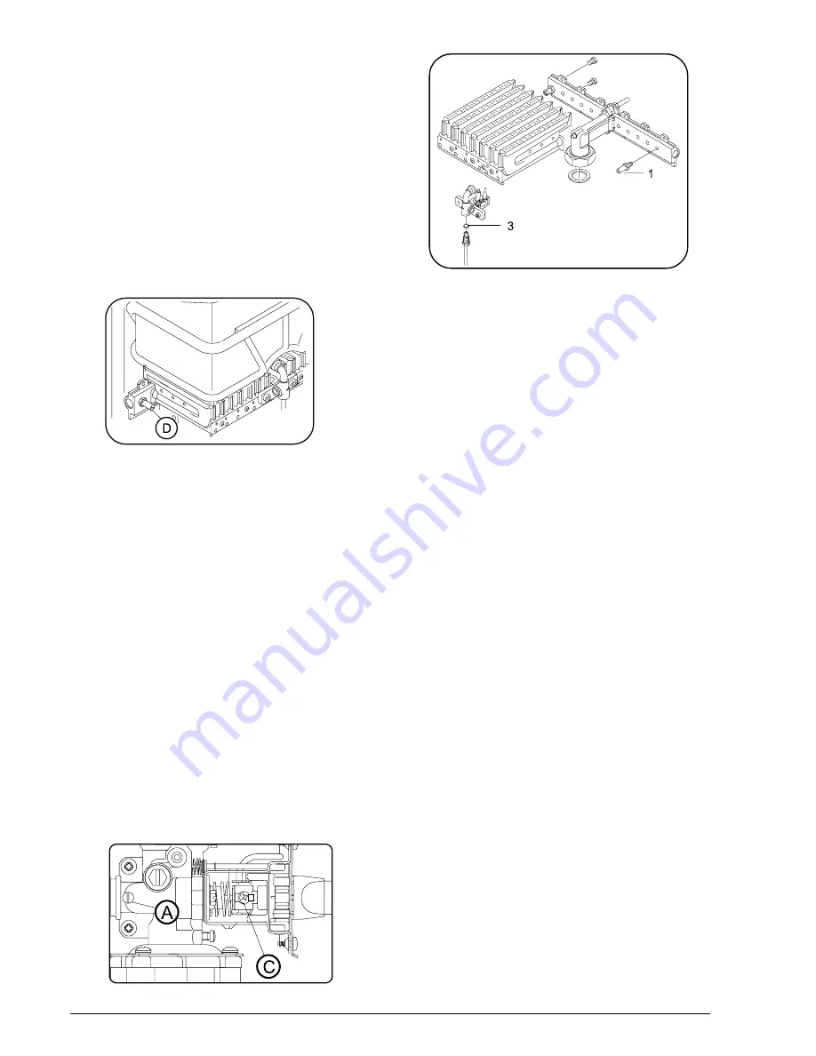
2. Remove the burner and replace the injectors (diagram 7,
item 1);
3. Replace the pilot gas injector (diag. 7, item 3);
4. Replace the vacuum chamber if converting from LP to
NG. Pressure regulator also required.
5. Replace the main poppet valve head (diag.2, item 27);
6. Tighten the gas valve and check for possible leaks;
7. Note the new type of gas on the appliance's rating plate;
8. Finally, adjust the minimum gas flow of the appliance
using a suitable method, the most common one being
described below:
a) Select a manometer with a mbar or mm (H
2
O) scale;
b) Loosen sealing screw D in the burner pressure tap-off
point (diagram 5) and connect the manometer;
c) Open the gas isolating valve;
d) Start up the appliance with the output slide control at
the minimum output position;
e) Adjust the pressure using screw C (diagram 6), in
compliance with Section 2 Technical Data, page 4.
G662_042
Diagram 5
Gas burner pressure adjustment for minimum output
(see clause 4.3, section 8)
Gas inlet pressure adjustment
1.
Turn off gas supply.
2.
Remove inlet test point screw A.
3.
Attach U tube manometer.
4.
Turn on gas supply and start up appliance in accordance
with operating instructions.
5.
Check inlet gas pressure while appliance is operating.
6.
For natural gas appliances adjust pressure at appliance
regulator.
No adjustment for LP appliances, check cylinder
regulator and pipe size.
7.
Turn off gas supply, remove manometer, replace sealing
screw, turn on gas supply and test for leaks.


