


ELECTRICAL
CAUTION: ISOLATE THE MAINS
ELECTRICITY SUPPLY BEFORE STARTING
ANY WORK AND OBSERVE ALL
RELEVANT SAFETY PRECAUTIONS
Note: Mains supply to the boiler must be
through a fused double pole isolator situated
adjacent to the appliance. The isolator must
have a contact separation of 3mm minimum
in all poles.
There should be no external wiring centre.
A facia mounted twin channel programmer
must be used.
Timers available: 7 716 192 038,
7 716 192 039, 7 716 192 041.
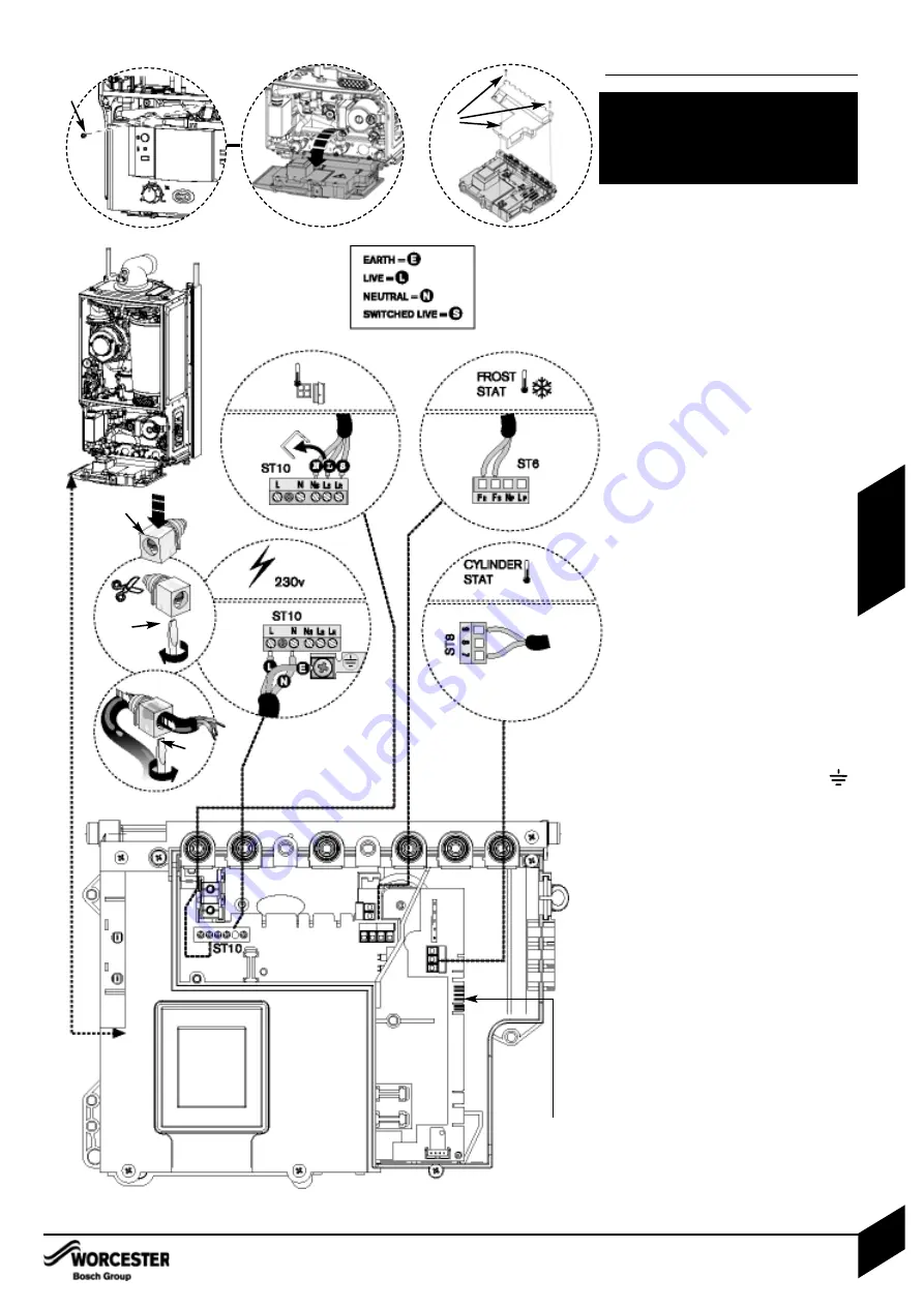
Access to electrical connections:
Remove boiler casing to access control panel.
1 Unscrew screw (A) and lower the control
box into the horizontal position.
2 Unscrew the three screws (B) in the control
panel and pull off the connections cover.
3 Unclip cable clamp (C).
4 Cut off the tapered cable entry to fit cable
diameter required.
5 Turn cable retaining screw (D) anti-clockwise.
Run cable over the main crossbar and
through the cable clamp (C), ensuring there
is ample cable to reach the connectors.
Turn cable clamping screw (D) clockwise to
secure cable and replace clamp (C) into
control panel.
6 Mains power 230v connection (ST10):
Separate wires from cable end and strip
to 6mm.
Connect LIVE wire to terminal (L)
Connect NEUTRAL wire to the terminal (N)
Connect EARTH wire to the connector
NOTE: Earth cable to be longer so that it
pulls out last if mains cable is snagged.
7 Optional external frost stat connection (ST6):
Connect frost stat wires to terminal (Fs) and (F
R
)
8
Central heating channel
230V room stat if required with timer
7 716 192 038 (ST10):
Remove link
Connect room stat LIVE supply to terminal (L
S
)
Connect room stat LIVE return to terminal (L
R
)
Connect room stat NEUTRAL to terminal (N
S
)
NOTE: If timer 7 716 192 039 or 7 716 192
041 is used, the roomstat is incorporated in
the transmitter. Therefore keep link fitted.
9
Hot water channel
Volt-free cylinder stat (ST8):
Cylinder Stat wires to terminals 7 and 9.
NOTE: The cylinder stat must be volt-free,
i.e not connected to any voltage source.
10
Diverter valve motor
(ST17):
Connect electrical harness from diverter valve
motor to ST17 (see following page).
2
B
3
C
4
5
D
D
6
7
8
ELECTRICAL
INSTALLATION & SERVICING INSTRUCTIONS FOR WORCESTER BOSCH GREENSTAR 12i System/24i System
8 716 107 375a (02/05)
27
IN
ST
AL
LA
TI
O
N
A
1
9
10


