background image

VideoJet X10 SN

Operation | en

93

Bosch Security Systems

Installation and Operating Manual

DOC | V4.0 | 2009.06

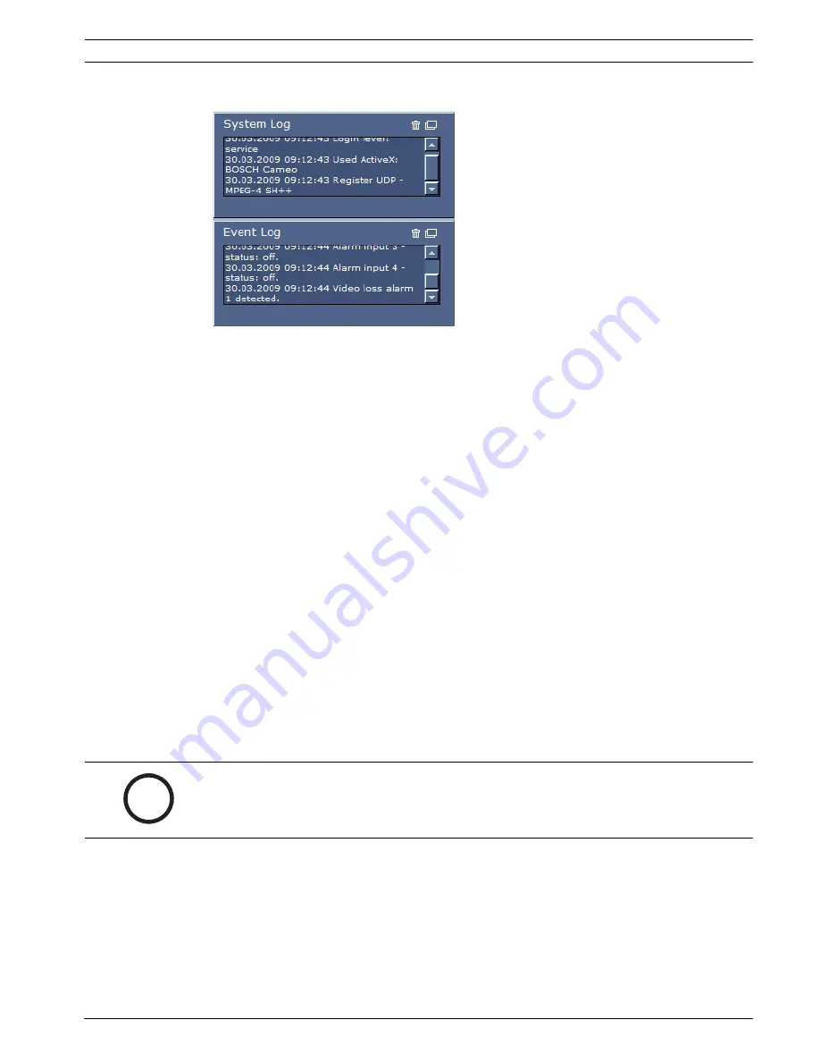
System Log / Event Log

The 

System Log

 field contains information about the operating status of the VideoJet X10 SN 

and the connection. You can save these messages automatically in a file (see 

Section 5.15 Advanced Mode: LIVEPAGE Functions, page 42

).

Events such as the triggering or end of alarms are shown in the 

Event Log

 field. You can save 

these messages automatically in a file (see 

Section 5.15 Advanced Mode: LIVEPAGE Functions, 

page 42

).

1.

If you want to delete the entries, click the delete icon in the top right-hand corner of the 

relevant field.

2.

If you want to view a detailed log, click the icon in the top right-hand corner of the 

relevant field. A new window will open.

Audio Function

Depending on the configuration, the VideoJet X10 SN can send and receive audio signals. All 

users who are connected by browsers receive the audio signals sent by the VideoJet X10 SN.

Audio signals can only be sent to the VideoJet X10 SN by the user who connects to the unit 

first.

1.

On the 

LIVEPAGE

, click anywhere next to the video image to remove the focus from the 

ActiveX.

2.

Hold down the 

F12

 key to make a voice connection to the VideoJet X10 SN. The 

browser's status bar displays the message 

Send Audio ON

.

3.

Release the 

F12

 key when you want to stop sending audio signals to the 

VideoJet X10 SN. The status bar in Internet Explorer displays the message 

Send Audio 

OFF

.

i

NOTICE! 

When the connection maintaining voice contact with the VideoJet X10 SN is broken, the next 

user to make a connection to the VideoJet X10 SN can send audio data to the 

VideoJet X10 SN.

Содержание VideoJet X10 SN

Страница 1: ...VideoJet X10 SN Network Video Server en Installation and Operating Manual ...

Страница 2: ...VideoJet X10 SN ...

Страница 3: ... 17 4 Installation 19 4 1 Preparations 19 4 2 Mounting 19 4 3 Connections 20 4 4 Power On Power Off 24 4 5 Setup Using the Configuration Manager 24 5 Configuration Using a Web Browser 27 5 1 Connecting 27 5 2 Configuration Menu 29 5 3 Basic Mode Unit Access 31 5 4 Basic Mode Date Time 32 5 5 Basic Mode Network 33 5 6 Basic Mode Encoder Profile 34 5 7 Basic Mode Audio 35 5 8 Basic Mode Recording 35...

Страница 4: ...72 5 35 Advanced Mode Alarm Inputs 73 5 36 Advanced Mode Relay 73 5 37 Advanced Mode COM1 75 5 38 Advanced Mode Network 76 5 39 Advanced Mode Advanced 79 5 40 Advanced Mode Multicasting 81 5 41 Advanced Mode JPEG Posting 82 5 42 Advanced Mode Encryption 83 5 43 Advanced Mode Maintenance 84 5 44 Advanced Mode Licenses 86 5 45 Advanced Mode System Overview 86 5 46 Function Test 87 6 Operation 89 6 1...

Страница 5: ...06 8 3 Malfunctions with iSCSI Connections 106 8 4 LEDs 107 8 5 Processor Load 108 8 6 Network Connection 108 8 7 Serial Interface 108 8 8 Terminal Block 109 8 9 Communication with Terminal Program 110 8 10 Copyrights 112 9 Specifications 113 9 1 Unit 113 9 2 Protocols Standards 114 10 Glossary 115 11 Index 119 ...

Страница 6: ...6 en Table of Contents VideoJet X10 SN DOC V4 0 2009 06 Installation and Operating Manual Bosch Security Systems ...

Страница 7: ...io and control signals over data networks Ethernet LAN Internet There are various memory options for recording the images captured by the connected camera The unit is intended for use with CCTV systems Various functions can be triggered automatically by incorporating external alarm sensors Other applications are not permitted In the event of questions concerning the use of the unit which are not a...

Страница 8: ... requirements of EU Directives 89 336 Electromagnetic Compatibility and 73 23 amended by 93 68 Low Voltage Directive 1 5 Rating Plate For exact identification the model name and serial number are inscribed on the bottom of the housing Please make a note of this information before installation if necessary so as to have it to hand in case of questions or when ordering spare parts ...

Страница 9: ... to rain or moisture if foreign bodies have penetrated the unit after long storage under adverse conditions or after exposure to extreme stress in transit 2 2 Installation and Operation The relevant electrical engineering regulations and guidelines must be complied with at all times during installation Relevant knowledge of network technology is required to install the unit Before installing or op...

Страница 10: ...10 en Safety Information VideoJet X10 SN DOC V4 0 2009 06 Installation and Operating Manual Bosch Security Systems ...

Страница 11: ...ct CD with the following content Quick Installation Guide Manual System Requirements document Further documentation on Bosch Security Systems products Configuration Manager MPEG ActiveX control Player and Archive Player DirectX control Microsoft Internet Explorer Sun JVM Adobe Acrobat Reader i NOTICE Check that the delivery is complete and in perfect condition Arrange for the unit to be checked by...

Страница 12: ...re for example VIDOS version 3 11 or higher or Bosch Video Management System version 2 02 or higher or MPEG 4 compatible hardware decoder from Bosch Security Systems for example VIP XD as a receiver and connected video monitor For playing back recordings connection to storage medium i NOTICE Also note the information in the System Requirements document on the product CD supplied If necessary you c...

Страница 13: ...IP XD can be used as receivers Computers with decoding software such as VIDOS or computers with the Microsoft Internet Explorer Web browser can also be used as receivers Video Encoding The VideoJet X10 SN uses the MPEG 4 and H 264 video compression standards Thanks to efficient encoding the data rate remains low even with high image quality and can also be adapted to local conditions within wide l...

Страница 14: ...ed to include special video analysis algorithms Snapshots Individual video frames snapshots can be called up as JPEG images by the VideoJet X10 SN stored on the computer s hard drive or displayed in a separate browser window Recordings Various local memory options enable the VideoJet X10 SN to be used as a digital VCR The VideoJet X10 SN supports ANR technology which guarantees seamless recording ...

Страница 15: ...sh cards for local storage USB interfaces for future WAN or WLAN connections Transparent bidirectional data channel via RS 232 RS 422 RS 485 serial interface Configuration and remote control of all internal functions via TCP IP also secured via HTTPS Password protection to prevent unauthorized connection or configuration changes Extensive flexible storage options Four alarm inputs and four relay o...

Страница 16: ... functions 2 Video In video input BNC socket for connecting the video source 3 Audio In audio line input 3 5 mm stereo socket for connecting an audio line input signal 4 Audio Out audio line output 3 5 mm stereo socket for connecting an audio line output signal 5 Connect LED flashes green when the unit is connected to a video 6 CF LED flashes orange when activity is detected on the CF card ...

Страница 17: ...it Base T 8 ETH LED lights up yellow when the unit is connected to the network via ETH 9 Terminal block for alarm inputs relay outputs serial interface and power supply 10 Factory reset button to restore factory default settings 11 Compact Flash slot for a CF card type I or type II i NOTICE For more information about the LEDs see Section 8 4 LEDs page 107 For terminal block assignment see Section ...

Страница 18: ...18 en Product Description VideoJet X10 SN DOC V4 0 2009 06 Installation and Operating Manual Bosch Security Systems ...

Страница 19: ...ide adequate cable strain relief where needed Avoid impacts blows and severe vibrations that exceed the specification limits see Section 9 Specifications page 113 as these can irreparably damage the unit 4 2 Mounting You can purchase a rack mount kit from Bosch Security Systems which is designed to accommodate three VideoJet X10 SN CAUTION The unit is intended for use indoors or in housings Select...

Страница 20: ...e VideoJet X10 SN with a 3 5 mm stereo plug 2 Connect a unit with line in connection to the Audio Out socket of the VideoJet X10 SN with a 3 5 mm stereo plug Network You can connect the VideoJet X10 SN to a 10 100 Base T network using a standard UTP category 5 cable with RJ45 plugs X Connect the VideoJet X10 SN to the network via the ETH socket CF Slot You can insert a type I or II CompactFlash ca...

Страница 21: ...al block see Section 8 8 Terminal Block page 109 The alarm inputs are used to connect to external alarm devices such as door contacts or sensors With the appropriate configuration an alarm sensor can automatically connect the VideoJet X10 SN to a remote location for example A zero potential closing contact or switch can be used as the actuator X Connect the lines to the appropriate terminals on th...

Страница 22: ...s information on the operational state of the unit and signals a unit defect see Section 8 4 LEDs page 107 You can connect an additional two color LED to the VideoJet X10 SN as a remote indicator This provides the same information as the integrated Connect LED A remote indicator can be useful if the VideoJet X10 SN is installed at a location that is difficult to access or see for example in a cabl...

Страница 23: ... BP and GND contacts The correct time is crucial for evaluating local recordings 1 Connect the plus line on the battery to the BP terminal on the orange terminal block 2 Connect the minus line on the battery to the GND terminal on the orange terminal block 3 Now check that the connections are secure CAUTION Connect only batteries with the following specification 10 to 30 V DC 50 Ah max 12 24 V con...

Страница 24: ... transmitted via the network 4 5 Setup Using the Configuration Manager The Configuration Manager program can be found on the product CD contained in the scope of delivery This program allows you to implement and set up new video servers in the network quickly and conveniently Installing the Program 1 Insert the CD into the computer s CD ROM drive 2 If the CD does not start automatically open the C...

Страница 25: ...popup menu 4 In the Unit IP address field enter a valid IP address for your network for example 192 168 0 110 and click OK The unit reboots and the IP address is valid 5 If required enter an appropriate subnet mask for the IP address and additional network data Reboot You can trigger the reboot directly with the assistance of the Configuration Manager X Right click the entry for the unit in the li...

Страница 26: ...26 en Installation VideoJet X10 SN DOC V4 0 2009 06 Installation and Operating Manual Bosch Security Systems ...

Страница 27: ...led Sun JVM Installing MPEG ActiveX Suitable MPEG ActiveX software must be installed on the computer to allow the live video images to be played back If necessary you can install the program from the product CD supplied 1 Insert the product CD into the computer s CD ROM drive If the CD does not start automatically open the root directory of the CD in Windows Explorer and double click MPEGAx exe 2 ...

Страница 28: ...ult address is preset at the factory 192 168 0 1 1 Start the Web browser 2 Enter the IP address of the VideoJet X10 SN as the URL The connection is established and after a short time you will see the LIVEPAGE with the video image Maximum Number of Connections If you do not connect the unit may have reached its maximum number of connections Depending on the unit and network configuration each Video...

Страница 29: ...ich contains all the unit s parameters arranged in groups You can view the current settings by opening one of the configuration screens You can change the settings by entering new values or by selecting a predefined value from a list field There are two options for configuring the unit or checking the current settings Basic mode Advanced mode In Basic Mode the most important parameters are arrange...

Страница 30: ...t window margin The corresponding submenu is displayed 2 Click one of the entries in the submenu The Web browser opens the corresponding page Making Changes Each configuration screen shows the current settings You can change the settings by entering new values or by selecting a predefined value from a list field X After each change click Set to save the change CAUTION Save each change with the ass...

Страница 31: ...Camera name stamping page 40 The camera name makes the task of administering cameras in larger video monitoring systems easier for example using the VIDOS or Bosch Video Management System programs Enter a unique unambiguous name for the camera in this field Password A VideoJet X10 SN is generally protected by a password to prevent unauthorized access to the unit You can use different authorization...

Страница 32: ...ting in your system or network it is important to synchronize their internal clocks For example it is only possible to identify and correctly evaluate simultaneous recordings when all units are operating on the same time If necessary you can synchronize the unit with your computer s system settings X Click the Sync to PC button to copy your computer s system time to the VideoJet X10 SN Time server...

Страница 33: ...e network for the dynamic assignment of IP addresses you can activate acceptance of IP addresses automatically assigned to the VideoJet X10 SN Certain applications VIDOS Bosch Video Management System Archive Player Configuration Manager use the IP address for the unique assignment of the unit If you use these applications the DHCP server must support the fixed assignment between IP address and MAC...

Страница 34: ...details are displayed in the list field Low bandwidth CIF High quality for low bandwidth connections resolution 352 288 240 pixels Low delay 2 3 D1 High quality with low delay resolution 464 576 480 pixels High resolution 4CIF D1 High resolution for high bandwidth connections resolution 704 576 480 pixels DSL For DSL connections with 500 kbps resolution 352 288 240 pixels ISDN 2B For ISDN connecti...

Страница 35: ...equire an additional bandwidth of approx 80 kbps for each connection If you do not want any audio data to be transmitted select Off Line In 1 You can set the line input gain Make sure that the display does not go beyond the green zone during modulation Line Out You can set the line output gain Make sure that the display does not go beyond the green zone during modulation 5 8 Basic Mode Recording Y...

Страница 36: ... ID Each VideoJet X10 SN should be assigned a unique identifier that you can enter here as an additional means of identification Device name You can give the VideoJet X10 SN a name to make it easier to identify The name makes the task of administering multiple units in larger video monitoring systems easier for example using the VIDOS or Bosch Video Management System programs i NOTICE You can sele...

Страница 37: ...r is inserted into the Result field 3 In the character map click the and icons to move between the different pages of the table or select a page from the list field 4 Click the icon to the right of the Result field to delete the last character or click the X icon to delete all characters 5 Now click the OK button to apply the selected characters to the second line of the Camera 1 parameters The wi...

Страница 38: ...ization level is live It can only be used to view the live video image and switch between the different live image displays You can define and change a password for each authorization level if you are logged in as service or if the unit is not password protected Enter the password for the appropriate authorization level here Confirm password In each case enter the new password a second time to eli...

Страница 39: ...and daylight saving time DST The unit already contains the data for DST switch overs up to the year 2018 You can use these data or create alternative time saving data if required 1 First check whether the correct time zone is selected If it is not correct select the appropriate time zone for the system and click the Set button 2 Click the Details button A new window will open and you will see the ...

Страница 40: ...3 Advanced Mode Display Stamping Various overlays or stamps in the video image provide important supplementary information These overlays can be enabled individually and are arranged on the image in a clear manner Camera name stamping This field sets the position of the camera name overlay It can be displayed at the Top at the Bottom or at a position of your choice that you can then specify using ...

Страница 41: ...e message to be displayed in the event of an alarm The maximum text length is 31 characters Video watermarking Choose On if you wish the transmitted video images to be watermarked After activation all images are marked with a green W A red W indicates that the sequence live or saved has been manipulated 5 14 Advanced Mode Appearance On this page you can adapt the appearance of the web interface an...

Страница 42: ...ou can choose between two given image sizes to display the M JPEG image on the LIVEPAGE JPEG interval You can specify the interval at which the individual images should be generated for the M JPEG image on the LIVEPAGE JPEG quality You can specify the image quality for displaying M JPEG on the LIVEPAGE 5 15 Advanced Mode LIVEPAGE Functions i NOTICE There are always two languages to choose from Eng...

Страница 43: ... is active the corresponding icon changes color Show relay outputs Relay outputs are shown next to the video image as icons along with their assigned names If the relay is switched the icon changes color Show VCA trajectories The trajectories motion lines of objects from the video content analysis are displayed in the live video image if a corresponding analysis type is activated see Section 5 31 ...

Страница 44: ...ectory Save system log Check this option to save system messages in a text file on your local computer You can then view edit and print this file with any text editor or the standard Office software File for system log 1 Enter the path for saving the system log here 2 If necessary click Browse to find a suitable directory 5 17 Advanced Mode Video Input You can activate the 75 Ohm terminating resis...

Страница 45: ...ion 0 255 You can use this function to adjust the color saturation so as to make the reproduction of colors on your monitor as realistic as possible Brightness 0 255 You can use this function to adapt the brightness of the video image to your working environment Low pass filter 0 255 You can use this function to filter very fine noise from the image This reduces and optimizes the bandwidth necessa...

Страница 46: ...operating environment for example network structure bandwidth data load To this end the VideoJet X10 SN simultaneously generates two data streams Dual Streaming which compression settings you can select individually for example one setting for transmissions to the Internet and one for LAN connections Pre programmed profiles are available each giving priority to different perspectives Low bandwidth...

Страница 47: ... You can switch between profiles by clicking the appropriate tabs Preview for Select which video data stream should be displayed in the previews You can deactivate the display of the video images if the performance of the computer is affected too strongly by the decoding of the data streams 1 Check the box for the required data stream 2 Click the i icon above the relevant preview to display furthe...

Страница 48: ...IF 176 144 120 pixels CIF 352 288 240 pixels 1 2 D1 352 576 480 pixels 2CIF 704 288 240 pixels 4CIF D1 704 576 480 pixels 2 3 D1 464 576 480 pixels Default Click Default to return the profile to the factory default values Details Clicking the Details button displays further details on image quality and data transmission These settings require extensive knowledge of the MPEG standard and video data...

Страница 49: ... a higher priority and only a small amount of power remains available for JPEG images The JPEG setting is suitable for applications that primarily require JPEG images for example JPEG recordings When this setting is made the amount of power available for video images will be reduced 5 20 Advanced Mode Audio You can set the gain of the audio signals to suit your specific requirements The current vi...

Страница 50: ... to the VideoJet X10 SN on various local storage media or on an appropriately configured iSCSI system CF cards see Section CF Slot page 20 are the ideal solution for shorter storage times and temporary recordings for example alarm recordings or local buffering in the event of network interruptions if the VideoJet X10 SN has a USB hard drive this is suitable for longer local recordings For long ter...

Страница 51: ...le storage media You can select individual media or iSCSI drives and transfer these to the Managed storage media list You can activate the storage media in this list and configure them for storage 1 In the Recording media section click the iSCSI Media and Local Media tabs to display the applicable storage media in the overview 2 In the Storage overview section double click the required storage med...

Страница 52: ...ium from the Managed storage media list It is then no longer used for recordings 1 Click a storage medium in the Managed storage media list to select it 2 Click the Remove button below the list The storage medium is deactivated and removed from the list 5 22 Advanced Mode Remote Video Device You can allow a remote video device to use the VideoJet X10 SN storage media This means you can record vide...

Страница 53: ...row to display the list of devices detected 3 Click the required device in the list to transfer its IP address 5 23 Advanced Mode Recording Profiles You can define up to ten different recording profiles You will then use these recording profiles in the recording scheduler where they are linked with the individual days and times see Section 5 25 Advanced Mode Recording Scheduler page 56 1 Click one...

Страница 54: ...e required pre alarm time from the list field Post alarm time You can select the required post alarm time from the list field Post alarm profile You can select the encoder profile to be used for recording during the post alarm time see Section 5 19 Advanced Mode Encoder Profile page 46 The Standard profile option adopts the selection at the top of the page Alarm input Motion alarm Video loss alarm...

Страница 55: ... used older recordings are only overwritten if the retention time entered here has expired Retention time Camera 1 Enter the required retention time in hours or days for each recording Recording 1 corresponds to Stream 1 Recording 2 corresponds to Stream 2 i NOTICE For more information please see the Alarm Task Script Language document and the RCP documentation These documents can be found on the ...

Страница 56: ...on In addition to the normal weekdays you can define holidays that are not in the standard weekly schedule on which recordings are to apply This allows you to apply a schedule for Sundays to other days with dates that fall on varying weekdays 1 Click the profile you want to link in the Time periods field 2 Click in a field in the table hold down the mouse button and drag the cursor over all the pe...

Страница 57: ...ny time 1 Click the Delete button A new window will open 2 Click the date you wish to delete 3 Click OK The item will be deleted from the table and the window will close 4 The process must be repeated for deleting additional days Time periods You can change the names of the recording profiles 1 Click a profile and then the Rename button 2 Enter your chosen name and then click the Rename button aga...

Страница 58: ...f these settings 5 27 Advanced Mode Alarm Connections You can select how the VideoJet X10 SN responds to an alarm In the event of an alarm the unit can automatically connect to a pre defined IP address You can enter up to ten IP addresses to which the VideoJet X10 SN will connect in sequence in the event of an alarm until a connection is made Connect on alarm Select On so that the VideoJet X10 SN ...

Страница 59: ...ber of destination IP address list field 2 Enter the address 0 0 0 0 in the Destination IP address field 3 Enter your chosen password in the Destination password field 4 Define this password as the user password for all remote stations to which a connection is to be possible Video transmission If the unit is operated behind a firewall TCP HTTP port should be selected as the transfer protocol For u...

Страница 60: ...er 2 SSL encryption The data for the connection for example the password can be securely transmitted with SSL encryption If you have selected the On option only encrypted ports are offered in the Remote port parameter You can activate and configure encryption of the media data video audio and metadata on the Encryption page see Section 5 42 Advanced Mode Encryption page 83 Auto connect Select the ...

Страница 61: ...s of image processing Such changes can be due to movements in the camera s field of view You can select various VCA configurations and adapt these to your application as required The Silent MOTION configuration is active by default In this configuration metadata is created to facilitate searches of recordings however no alarm is triggered 1 Select a VCA configuration and make the required settings...

Страница 62: ...oning configuration and test new settings You can use the saved configuration to restore the original settings at any time 1 Select a VCA profile and enter the required settings 2 If necessary click the Default button to return all settings to their default values i NOTICE If computing power becomes short the highest priority is always the live images and recordings This can lead to impairment of ...

Страница 63: ...deo image in the preview window next to the parameter settings With the MOTION analysis type for example the sensor fields in which motion is recorded will be marked with rectangles Motion detector MOTION only For the detector to function the following conditions must be met Analysis must be activated At least one sensor field must be activated The individual parameters must be configured to suit ...

Страница 64: ...ary click Select All to select the entire video frame for monitoring 5 Right click any fields you wish to deactivate 6 Click OK to save the configuration 7 Click the close button X in the window title bar to close the window without saving the changes Tamper detection You can reveal the tampering of cameras and video cables by means of various options Run a series of tests at different times of th...

Страница 65: ...this function if tampering associated with EMC interference noisy scene as the result of a strong interference signal in the vicinity of the video lines as an example should trigger an alarm Reference check You can save a reference image that is continuously compared with the current video image If the current video image in the marked areas differs from the reference image an alarm is triggered T...

Страница 66: ... the window without saving the changes 5 30 Advanced Mode VCA Scheduled This configuration allows you to link the created VCA profile with the days and times at which the video content analysis is to be active You can link any number of 15 minute intervals with the VCA profiles for each day of the week Moving the mouse cursor over the table displays the time below it This aids orientation In addit...

Страница 67: ...ferent to the standard weekly schedule This allows you to apply a schedule for Sundays to other days with dates that fall on varying weekdays 1 Click the Holidays tab Any days that have already been selected will be shown in the table 2 Click the Add button A new window will open 3 Select the desired date from the calendar You can select several consecutive calendar days by holding down the mouse ...

Страница 68: ...configuration in which metadata is created is active this metadata facilitates searches of recordings but does not trigger an alarm Trigger You can select one of the physical alarms on the device s alarm inputs or one of the virtual alarms as a trigger A virtual alarm is created using software with RCP commands or alarm scripts for example i NOTICE For more information please see the Alarm Task Sc...

Страница 69: ...elect the delay period here for the reaction of the video content analysis to trigger signals A delay period may be useful in avoiding false alarms or frequent triggering for example During the delay period the Silent MOTION configuration is always enabled 5 32 Advanced Mode Audio Alarm The VideoJet X10 SN can create alarms on the basis of audio signals You can configure signal strengths and frequ...

Страница 70: ... sensitivity Signal Ranges You can exclude particular signal ranges in order to avoid false alarms For this reason the total signal is divided into 13 tonal ranges mel scale Check or uncheck the boxes below the graphic to include or exclude individual ranges 5 33 Advanced Mode Alarm E Mail As an alternative to automatic connecting alarm states can also be documented by e mail In this way it is pos...

Страница 71: ...il to SMS gateway for example to send an alarm by cellphone without an image attachment Attach JPEG from camera Click the checkbox to specify that JPEG images are sent from the camera An enabled video input is indicated by a check mark Destination address Enter the e mail address for alarm e mails here The maximum address length is 49 characters Sender name Enter a unique name for the e mail sende...

Страница 72: ...ask Editor field or change existing scripts in line with your requirements 3 When you are finished click the Set button to transmit the scripts to the unit If the transfer was successful the message Script successfully parsed is displayed over the text field If it was not successful an error message will be displayed with further information CAUTION Editing scripts on this page overwrites all sett...

Страница 73: ...anced Mode Relay You can configure the switching behavior of the relay outputs For each relay you can specify an open switch relay normally closed contact or a closed switch relay normally open contact You can also specify whether an output should operate as a bistable or monostable relay In bistable mode the triggered state of the relay is maintained In monostable mode you can set the time after ...

Страница 74: ...rigger by interruption of the video signal Motion alarm Trigger by motion alarm as configured on the VCA page see Section 5 31 Advanced Mode VCA Event Triggered page 68 Local input Trigger by the corresponding external alarm input Remote input Trigger by remote station s corresponding switching contact only if a connection exists Relay name You can assign a name for the relay here The name is show...

Страница 75: ...t the value for the transmission rate in bps Data bits The number of data bits per character cannot be changed Stop bits Select the number of stop bits per character Parity check Select the type of parity check Interface mode Select the desired protocol for the serial interface i NOTICE If the VideoJet X10 SN is working in multicast mode see Section 5 40 Advanced Mode Multicasting page 81 the firs...

Страница 76: ...ode Network The settings on this page are used to integrate the VideoJet X10 SN into an existing network Some changes only take effect after the unit is rebooted In this case the Set button changes to Set and Reboot 1 Make the desired changes 2 Click the Set and Reboot button The VideoJet X10 SN is rebooted and the changed settings are activated ...

Страница 77: ...he unit can use a DNS server to trigger an address specified as a name Enter the IP address of the DNS server here Video transmission If the unit is operated behind a firewall TCP HTTP port should be selected as the transfer protocol For use in a local network select UDP HTTP browser port Select a different HTTP browser port from the list if required The default HTTP port is 80 If you want to allo...

Страница 78: ...f 1 514 bytes in UDP mode iSCSI MSS Byte You can specify a higher MSS value for a connection to the iSCSI system than for the other data traffic via the network The potential value depends on the network structure A higher value is only useful if the iSCSI system is located in the same subnet as the VideoJet X10 SN Enable DynDNS DynDNS org is a DNS hosting service that stores IP addresses in a dat...

Страница 79: ... and no more than once a day to avoid the possibility of being blocked by the service provider To transfer the IP address of the VideoJet X10 SN click the Register button Status The status of the DynDNS function is displayed here for information purposes You cannot change any of these settings 5 39 Advanced Mode Advanced The settings on this page are used to implement advanced settings for the net...

Страница 80: ... of one or two required target units here SNMP traps You can select which traps are to be sent 1 Click Select A list is opened 2 Click the checkboxes to select the required traps All the checked traps will be sent 3 Click Set to accept the selection Authentication If a RADIUS server is employed in the network for managing access rights authentication must be activated here to allow communication w...

Страница 81: ...ol IGMP V2 The address range is from 225 0 0 0 to 239 255 255 255 The multicast address can be the same for multiple streams However it will be necessary to use a different port in each case so that multiple data streams are not sent simultaneously using the same port and multicast address Enable To enable simultaneous data reception on several receivers you need to activate the multicast function...

Страница 82: ...t required Multicast packet TTL You can enter a value to specify how long the multicast data packets are active on the network This value must be greater than one if multicast is to be run via a router 5 41 Advanced Mode JPEG Posting You can save individual JPEG images on an FTP server at specific intervals You can then retrieve these images at a later date to reconstruct alarm events if required ...

Страница 83: ... will be sent to an FTP server Enter zero if you do not want any images to be sent FTP server IP address Enter the IP address of the FTP server on which you wish to save the JPEG images FTP server login Enter your login name for the FTP server FTP server password Enter the password that gives you access to the FTP server Path on FTP server Enter the exact path on which you wish to post the images ...

Страница 84: ...lash EPROM is reprogrammed The time remaining is shown by the message going to reset Reconnecting in seconds The unit reboots automatically once the upload has successfully completed If the Connect LED lights up red the upload has failed and must be repeated To perform the upload you must now switch to a special page 1 In the address bar of your browser enter main htm after the IP address of the V...

Страница 85: ...SSL certificate To be able to work with an SSL encrypted data connection both ends of a connection must hold the relevant certificates You can upload the SSL certificate comprising one or multiple files onto the VideoJet X10 SN If you wish to upload multiple files onto the VideoJet X10 SN you must select them consecutively 1 Enter the full path of the file to upload or click Browse to select the r...

Страница 86: ...vanced Mode System Overview The data on this page are for information purposes only and cannot be changed Keep a record of this information in case technical assistance is required i NOTICE The activation key cannot be deactivated again and is not transferable to other units i NOTICE You can select all required text on this page with the mouse and copy it to the clipboard with the Ctrl C key combi...

Страница 87: ... correctly after installation and configuration The function test is the only way to ensure that the VideoJet X10 SN operates as expected in the event of an alarm Your check should include the following functions Can the VideoJet X10 SN be called up remotely Does the VideoJet X10 SN transmit all the required data Does the VideoJet X10 SN respond to alarm events as required Do the recordings occur ...

Страница 88: ...88 en Configuration Using a Web Browser VideoJet X10 SN DOC V4 0 2009 06 Installation and Operating Manual Bosch Security Systems ...

Страница 89: ...ctiveX software must be installed on the computer to allow the live video images to be played back If necessary you can install the program from the product CD supplied 1 Insert the product CD into the computer s CD ROM drive If the CD does not start automatically open the root directory of the CD in Windows Explorer and double click MPEGAx exe 2 Follow the on screen instructions i NOTICE Also not...

Страница 90: ... VideoJet X10 SN within your network it must have a valid IP address for your network and a compatible subnet mask The following default address is preset at the factory 192 168 0 1 1 Start the Web browser 2 Enter the IP address of the VideoJet X10 SN as the URL The connection is established and after a short time you will see the LIVEPAGE with the video image ...

Страница 91: ...ia VIDOS or Bosch Video Management System Protected VideoJet X10 SN If the VideoJet X10 SN is password protected against unauthorized access the Web browser displays a corresponding message and prompts you to enter the password when you attempt to access protected areas 1 Enter the user name and associated password in the corresponding text fields 2 Click OK If the password is entered correctly th...

Страница 92: ...or over the video image Additional options for controlling peripherals are displayed with the mouse cursor Digital I O The alarm icons Input 1 to Input 4 are for information purposes and indicate the status of an alarm input When an alarm is triggered the corresponding icon lights up blue The unit s configuration determines whether the alarm is displayed as well as additional details see Section 5...

Страница 93: ...corner of the relevant field A new window will open Audio Function Depending on the configuration the VideoJet X10 SN can send and receive audio signals All users who are connected by browsers receive the audio signals sent by the VideoJet X10 SN Audio signals can only be sent to the VideoJet X10 SN by the user who connects to the unit first 1 On the LIVEPAGE click anywhere next to the video image...

Страница 94: ...is only visible if the unit is configured to enable this process see Section Allow local recording page 43 1 Click the icon to start recording The storage location depends on the configuration of the VideoJet X10 SN see Section Path for JPEG and MPEG files page 44 A red dot in the icon indicates that recording is in progress 2 Click the icon again to stop recording Image Resolution Sequences are s...

Страница 95: ...Click the RECORDINGS link in the navigation bar in the upper section of the window The playback page appears Camera Here you can select the camera from which you want to view the recordings Playback of the recordings starts immediately in the video window Recording Here you can select the recording that you want to view Playback of the recording starts immediately in the video window Controlling a...

Страница 96: ...to control playback speed Bookmarks In addition you can set markers in the sequences so called bookmarks and jump directly to these These bookmarks are indicated as small yellow arrows above the time interval Use the bookmarks as follows X Right click a bookmark to delete it Trick Mode If you are using a mouse with a scroll wheel you can view recordings frame by frame in trick mode To do this plac...

Страница 97: ... s CD ROM drive If the CD does not start automatically open the CD in Windows Explorer and double click the index html file to start the menu 2 From the list field at the top select the language you require and click Tools in the menu 3 Click the Archive Player option The installation will start Follow the instructions in the installation program The Archive Player will be installed at the same ti...

Страница 98: ...e receiver in a closed network an alarm a terminal program or Internet Explorer Connecting on Alarm With the appropriate configuration a connection between a sender and a receiver is made automatically when an alarm is triggered see Section 5 27 Advanced Mode Alarm Connections page 58 After a short time the live video image from the sender appears on the connected monitor This option can also be u...

Страница 99: ...o switch to the IP menu 2 Enter the command 4 in the IP menu to change the remote IP address then enter the IP address of the unit you wish to connect to 3 Enter the command 0 to return to the main menu and then enter the command 4 to switch to the Rcp menu 4 In the Rcp menu enter the command 5 to activate the automatic connection Closing the Connection with a Terminal Program 1 Start the terminal...

Страница 100: ...IP video security solution that enables the seamless management of digital video audio and data over any IP network It was developed for use with Bosch CCTV products as one component of an extensive video security management system It allows you to integrate your existing components into a simple to control system or into the entire Bosch range benefiting from a complete security solution based on...

Страница 101: ...ges to the settings are overwritten by the factory defaults A reset may be necessary for example if the unit has invalid settings that prevent it from functioning as desired 1 If necessary back up the current configuration using the Download button on the Maintenance configuration page see Section 5 43 Advanced Mode Maintenance page 84 2 Using a pointed object press the Factory Reset button locate...

Страница 102: ...ether with this installation and operating manual Your Bosch product is designed and manufactured with high quality materials and components which can be recycled and reused This symbol means that electrical and electronic equipment at their end of life should be disposed of separately from your household waste In the European Union there are separate collection systems for used electrical and ele...

Страница 103: ...u can view a range of information about your unit version on the System Overview page see Section 5 45 Advanced Mode System Overview page 86 Make a note of this information before contacting Customer Service You can download an internal maintenance log from the unit on the Maintenance page if you wish to send it to Customer Service by e mail see Section Maintenance log page 85 The following tables...

Страница 104: ...ect local monitor to the camera and check the camera function Faulty cable connections Check all cables plugs contacts and connections No connection established no image transmission The unit s configuration Check all configuration parameters Faulty installation Check all cables plugs contacts and connections Wrong IP address Check the IP addresses terminal program Faulty data transmission within ...

Страница 105: ... fitted The interface parameters do not match those of the other unit connected Make sure that the settings of all units involved are compatible The unit is not operational after a firmware upload Power failure during programming by firmware file Have the unit checked by Customer Service and replace if necessary Incorrect firmware file Enter the IP address of the unit followed by main htm in your ...

Страница 106: ... LUN mapping during iSCSI system configuration Check the iSCSI system configuration and reconnect After connecting to the iSCSI destination LUN FAIL appears below a node The LUN list could not be read as it was assigned to the wrong network interface Check the iSCSI system configuration and reconnect LUN mapping is not possible Some iSCSI systems do not support the use of an initiator extension De...

Страница 107: ...ions of possible malfunctions ETH LED Connect LED CF LED Does not light up No network connection Lights up yellow Network connection established Flashes yellow Data being transmitted over the network Lights up red Startup in progress Lights up green Startup complete VideoJet X10 SN is operational Flashes green Video connection established Flashes red VideoJet X10 SN is faulty for example following...

Страница 108: ...ats configured 1 Move the cursor over the graphic indicator Some additional numerical values are also displayed 2 Click the graphic indicator Further details are displayed 8 6 Network Connection You can display information about the network connection To do this move the cursor over the i icon 8 7 Serial Interface Options for using the serial interface include transferring transparent data control...

Страница 109: ...s see Section Remote Indication of the Connection Status page 22 For the backup power supply specifications see Section Backup Power Supply page 23 Contact RS 232 mode RS 422 mode RS 485 mode CTS CTS clear to send RxD receive data minus Data TXD TxD transmit data TxD transmit data minus RTS RTS ready to send TxD transmit data plus Data RXD RxD receive data RxD receive data plus GND GND ground Cont...

Страница 110: ...ore working with the terminal program 2 Connect the serial interface of the VideoJet X10 SN using any available serial interface on the computer Configuring the Terminal Before the terminal program can communicate with the VideoJet X10 SN the transmission parameters must be matched Make the following settings for the terminal program 19 200 bps 8 data bits No parity check 1 stop bit No protocol Co...

Страница 111: ...terminal program displays the current IP address and prompts you to enter a new IP address 5 Enter the desired IP address and press Enter The terminal program displays the new IP address 6 Use the displayed commands for any additional settings you require Reboot Briefly interrupt the power supply to the VideoJet X10 SN for a reboot disconnect the power supply unit from the mains supply and switch ...

Страница 112: ...Equipment Corporation Permission to use copy modify distribute and sell this software and its documentation for any purpose and without fee is hereby granted provided that the above copyright notices appear in all copies and that both those copyright notices and this permission notice appear in supporting documentation and that the names of Adobe Systems and Digital Equipment Corporation not be us...

Страница 113: ... 4 push in terminal 30 Vp p 2 A SELV 8 contacts Video input 1 BNC socket 0 7 to 1 2 Vp p 75 Ohm PAL NTSC Audio input Line In 1 3 5 mm stereo socket 5 5 Vp p max impedance 9 kOhm typ Audio output Line Out 1 3 5 mm stereo socket 3 0 Vp p max at impedance 10 kOhm typ 1 7 Vp p max at impedance 16 Ohm typ Displays 2 LED operating voltage video connection CF card on the front panel 1 LED network connect...

Страница 114: ...resolutions PAL NTSC 704 576 480 pixels 4CIF D1 704 288 240 pixels 2CIF 464 576 480 pixels 2 3 D1 352 576 480 pixels 1 2 D1 352 288 240 pixels CIF 176 144 120 pixels QCIF Total delay 120 ms PAL NTSC MPEG 4 no network delay Image refresh rate 25 30 ips max Network protocols RTP Telnet UDP TCP IP HTTP HTTPS DHCP IGMP V2 IGMP V3 ICMP RTSP FTP ARP SNTP SNMP V1 MIB II 802 1x Audio coding protocol G 711...

Страница 115: ...torage media amongst other things Used in computers in the form of CF cards digital cameras and Personal Digital Assistants PDA CIF Common Intermediate Format video format with 352 288 240 pixels D DHCP Dynamic Host Configuration Protocol uses an appropriate server to enable dynamic assignment of an IP address and other configuration parameters to computers on a network Internet or LAN DNS Domain ...

Страница 116: ... usually written in dotted decimal notation for example 209 130 2 193 iSCSI Storage over IP process for storage networks specifies how storage protocols are operated over IP ISDN Integrated Services Digital Network J JPEG An encoding process for still images Joint Photographic Experts Group K kbps Kilobits per second the actual data rate L LAN See Local Area Network Local Area Network A communicat...

Страница 117: ...rs Values used for configuration Q QCIF Quarter CIF video format with 176 144 120 pixels R RADIUS server Remote Authentication Dial In User Service a client server protocol for the authentication authorization and accounting of users with dial up connections on a computer network RADIUS is the de facto standard for central authentication of dial up connections via Modem ISDN VPN Wireless LAN see 8...

Страница 118: ...ansmission Control Protocol Telnet Login protocol with which users can access a remote computer Host on the Internet TLS Transport Layer Security TLS 1 0 and 1 1 are the standard advanced developments of SSL 3 0 see SSL TTL Time To Live life cycle of a data packet in station transfers U UDP User Datagram Protocol URL Uniform Resource Locator UTP Unshielded Twisted Pair W WAN See Wide Area Network ...

Страница 119: ...its 75 Data interface 21 Data terminal 110 Date 39 Date format 39 Daylight saving time 39 Default 48 54 61 62 Default profile 48 Deleting recordings 52 Device ID 36 Device name 31 36 DHCP server 33 Display stamping 40 Dome camera 21 Dual Streaming 13 46 DynDNS 78 E Echo 110 Electromagnetic compatibility 8 E mail 70 Encoder load 108 Encoding 13 Encryption protocol 77 EPROM 84 Establishing the conne...

Страница 120: ...80 Rear panel connections 17 Reboot 25 111 Receiver 13 Receiver password 59 Recording media 51 Recording profiles 53 Recording program 94 Recording scheduler 56 Recording status 57 Recording video sequences 94 Reflections of light 63 Regulations 7 Relay 17 22 Relay output 73 Relay outputs 22 Remote control 14 Remote indication 22 Remote LED 22 Repair 9 102 Reset 17 101 Router 82 S Safety 9 Saturat...

Страница 121: ...ission rate 75 Transmission standards 21 108 Transparent 75 Traps 80 Trick mode 96 Trigger 21 Trigger relay 74 TTL 82 U UDP 59 77 Unicast 81 Unit date 39 Unit identification 31 36 Unit name 31 36 Unit reset 101 Unit time 32 39 URL 28 90 USB interface 16 User name 31 38 V Value 45 VCR 44 Video content analysis 61 Video input 44 Video sensor 61 VRM 50 W Watermarking 41 ...

Страница 122: ...122 de Index VideoJet X10 SN DOC V4 0 2009 06 Installations und Bedienungshandbuch Bosch Security Systems ...

Страница 123: ......

Страница 124: ...Bosch Sicherheitssysteme GmbH Robert Koch Straße 100 85521 Ottobrunn Germany Telefon 089 6290 0 Fax 089 6290 1020 www boschsecurity com Bosch Sicherheitssysteme GmbH 2009 ...

Отзывы: