background image

“READ ALL INSTRUCTIONS” — Failure to follow the SAFETY RULES identified by
BULLET (•) symbol listed BELOW and other safety precautions, may result in serious

personal injury.

General Safety Rules for Bench Top Tools

!

WARNING

Safety

Work Area

•  

Keep work area clean and well lit.  

Cluttered

benches and dark areas invite accidents.

•  

Do  not  operate  power  tools  in  explosive 
atmospheres,  such  as  in  the  presence  of 
flammable liquids, gases or dust.

Power tools 

create sparks which may ignite the dust or fumes.

•  

Keep bystanders, children and visitors away
while  operating  a  power  tool.

Distractions 

can cause you to lose control.

•  

Store idle tools out of reach of children and
other untrained persons.  

Tools are dangerous

in the hands of untrained users.

•  

Do  not  leave  tool  running  unattended,  turn
power off.  

Do not leave tool until it comes to a

complete stop.

•  

MAKE  WORKSHOp  CHIlDpROOf 

with  pad

lock, master switches, or by removing starter keys.

Electrical Safety

•  

Before  plugging  in  the  tool,  be  certain  the 
outlet voltage supplied is compatible with the
voltage marked on the nameplate within 10%.

An outlet voltage incompatible with that specified
on the nameplate can result in serious hazards
and damage to the tool.

•  

Avoid body contact with grounded surfaces
such as pipes, radiators, ranges and refriger-
ators. 

There is an increased risk of electric shock

if your body is grounded.

•  

Do  not  expose  power  tools  to  rain  or  wet 
conditions.

Water  entering  a  power  tool  will 

increase the risk of electric shock.

•  

Do not abuse the cord.  Never use the cord to
carry the tools or pull the plug from an outlet.
Keep cord away from heat, oil, sharp edges or
moving parts.  Replace damaged cords imme-
diately.   

Damaged  cords  increase  the  risk  of 

electric shock.

•  

When operating a power tool outside, use an
outdoor extension cord marked “W-A” or “W”.

These cords are rated for outdoor use and reduce
the risk of electric shock.

personal Safety

•  

Stay alert, watch what you are doing and use
common sense when operating a power tool.

A moment of inattention or use of drugs, alcohol
or medication while operating power tools can be
dangerous.

•  

Dress properly.  Do not wear loose clothing or
jewelry.    Contain  long  hair.  Keep  your  hair,
clothing and gloves away from moving parts.

Loose clothes, jewelry or long hair can be caught
in moving parts. Roll long sleeves above elbows.
Rubber gloves and non-skid footwear are recom-
mended when working outdoors. 

•  

Avoid accidental starting.  Be sure switch is
“Off” before plugging in.

Carrying tools with

your finger on the switch or plugging in tools that
have the switch “ON” invites accidents.

•  

Remove adjusting keys or wrenches before
turning the tool “ON”.

A wrench or a key that is

left attached to a rotating part of the tool will be
thrown.

•  

Do  not  overreach,  keep  proper  footing  and
balance at all times.

Proper footing and balance

enables better control of the tool in unexpected 
situations.

•  

Do not stand on tool or its stand.

Serious injury

may occur if the tool is tipped or if the cutting tool
is accidentally contacted.  Do not store materials
on  or  near  the  tool  such  that  it  is  necessary  to
stand on the tool or its stand to reach them.

•  

Use  safety  equipment.   Always  wear  safety
goggles.

Dust mask, safety shoes, hard hat or

hearing protection must be used for appropriate
conditions.  Everyday  eyeglasses  only  have 
impact resistant lenses, they are NOT safety glasses.

Tool Use and Care

•  

Use clamps or other practical way to secure
and  support  the  workpiece  to  a  stable 
platform.

Holding the work by hand or against

your body is unstable.  It allows for work to shift,
causes binding of the tool and loss of control.

•  

Do not force tool.  Use the correct tool for your
application.

The correct tool will do the job better

“SAVE THESE INSTRUCTIONS”

-2-

BM 2610019162 10-11:BM 2610019162 10-11.qxp  10/20/11  8:59 AM  Page 2

Содержание TC10

Страница 1: ...onnement sécurité Instrucciones de funcionamiento y seguridad 1 877 BOSCH99 1 877 267 2499 www boschtools com Call Toll Free for Con sumer Information Service Locations Pour obtenir des informations et les adresses de nos centres de service après vente appelez ce numéro gratuit Llame gratis para obtener información para el consumidor y ubicaciones de servicio TC10 BM 2610019162 10 11 BM 2610019162...

Страница 2: ...rked W A or W These cords are rated for outdoor use and reduce the risk of electric shock personal Safety Stay alert watch what you are doing and use common sense when operating a power tool A moment of inattention or use of drugs alcohol or medication while operating power tools can be dangerous Dress properly Do not wear loose clothing or jewelry Contain long hair Keep your hair clothing and glo...

Страница 3: ...could cause serious hazard When servicing a tool use only identical replacement parts follow instructions in the Maintenance section of this manual Use of unauthorized parts or failure to follow Maintenance Instructions may create a hazard SAVE THESE INSTRUCTIONS READ ALL INSTRUCTIONS Failure to follow the SAFETY RULES identified by BULLET symbol listed BELOW and other safety precautions may resul...

Страница 4: ...g set tings NEVER place your fingers and hands in the path of the sawblade or other cutting tool DO NOT perform any operation fREEHAND always use the fence to position and guide the work for all cuts Empty water from tile saw base before trans poring Water left in base can splash into electrical components Some dust created by power sanding sawing grinding drilling and other construction activitie...

Страница 5: ...MANUAl THEY SERVE AS A REMINDER Of All SAfETY RUlES NEEDED fOR SAfE OpERATION Of THIS TIlE SAW READ ALL INSTRUCTIONS Failure to follow the SAFETY RULES identified by BULLET symbol listed BELOW and other safety precautions may result in serious per sonal injury WARNING Safety WARNING SAVE THESE INSTRUCTIONS BM 2610019162 10 11 BM 2610019162 10 11 qxp 10 20 11 8 59 AM Page 5 ...

Страница 6: ...re action could cause your hands to hit the tool If power cord is worn cut or dam aged in any way have it replaced immediately to avoid shock or fire hazard Your unit is for use on 120 volts and is equipped with a 3 conductor cord and grounding type plug approved by Under writers Laboratories and the Canadian Standards Associa tion The ground conductor has a green jacket and is attached to the too...

Страница 7: ...e extension cords are identified by a marking Acceptable for use with outdoor appli ances store indoors while not in use Use only ex tension cords having an electrical rating equal to or greater than the rating of the product Do not use damaged extension cords Examine the extension cord before using and replace it if it is damaged Do not abuse extension cords and do not yank on any cord to disconn...

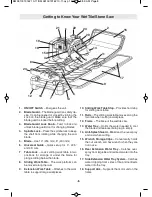
Страница 8: ...tension Work Table Attaches to the work table to support large workpieces 10 Sliding Work Table Stop Provides hard stop for sliding work table 11 Rails The sliding work table moves along the two rails when cutting a workpiece 12 frame The base of the wet tile saw 13 Water Tray Holds the water needed to cool the blade and features drain plug to empty 14 Anti Splash Guard Minimizes the over spray an...

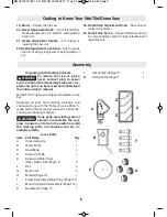
Страница 9: ...e 1 D Extension Table 1 E Extension Water Trays Rear Side A B Page 10 3 F Bolt 4 G Bolt Cover 4 H Manual Page 10 1 I Frame Assembly Water Tray Page 10 1 J Motor Support Arm Assembly Page 10 1 K Nut Wrench Page 11 1 L Hex Wrench Page 11 1 M Sliding Table Page 11 1 Assembly Getting to Know Your Wet Tile Stone Saw 19 Motor Powers the tile saw 20 Bevel Adjustment Knob To tilt the head for making bevel...

Страница 10: ...J E I M Operating Safety Instructions H Assembly 10 BM 2610019162 10 11 BM 2610019162 10 11 qxp 10 20 11 8 59 AM Page 10 ...

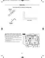
Страница 11: ... 1 Position the motor support arm assembly onto the frame assembly Fig 1 2 Using the hex wrench supplied install the four bolts and tighten Fig 1 3 Then place the four bolt covers on the bolts Assembly FIG 1 Tools Needed for Assembly And Alignment Nut Wrench Included Hex Wrench Included l K Framing square 11 BM 2610019162 10 11 BM 2610019162 10 11 qxp 10 20 11 8 59 AM Page 11 ...

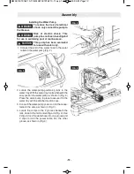
Страница 12: ...the water tray in place beneath the saw position the water pump as shown in Fig 2 Press the water pump in place to secure it to the water tray with the attached suction cups 3 Connect the water pump power cord to the recep tacle on the saw as shown in Fig 3 4 Locate the 4 clips in the 2 grooves beneath the rails close to the motor mounting arm Fig 4 Use 2 clips to lock the water hose into one groo...

Страница 13: ...til the tray slides under the two tabs 2 Once properly aligned lower the tray and it will lock into place under the tabs Fig 7 3 Install Part B by aligning the two tabs of the tray with the slots on the back edges of Part A Once aligned tilt Part B tabs at an angle until it slides into Part A slots and lower so Part B is in line with Part A for proper water flow Rear Extension Water Tray Align the...

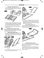
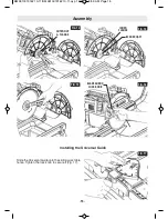
Страница 14: ...uter flange Re move the old blade Leave the inner flange on the blade shaft Fig 13 14 4 Place new blade on blade shaft Fig 14 Ensure the blade direction arrow points in the same direction as the arrow marked on the blade guard 5 Reinstall the outer flange and nut Press the spin dle lock with one hand and tighten the nut clock wise with the supplied wrench Close and tighten the blade guard lock kno...

Страница 15: ...GE BLADE SHAFT BLADE GUARD LOCK KNOB Slide the Universal Guide onto the sliding work table fence Tighten the lock knob to secure it Fig 17 FIG 17 Assembly Installing the Universal Guide 15 BM 2610019162 10 11 BM 2610019162 10 11 qxp 10 20 11 8 59 AM Page 15 ...

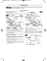
Страница 16: ...ng the head down with hand turn the depth stop adjustment knob to raise or lower the lowest position of the blade 4 Tighten the locking nut 5 Tighten the depth stop adjustment knob and depth adjustment lock knob NOTE To cut all the way through the workpiece make sure that the lowest position of the blade is 3 16 5 mm below the surface of the work table Fig 20 FIG 19 DEPTH STOP ADJUSTMENT KNOB DEPT...

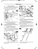
Страница 17: ...en the lever to lock the uni versal guide at the desired angle For straight cutting the universal guide is used as rip fence Fig 23 1 Set the angle to 0 2 Loosen the universal guide lock knob and position the guide to the desired distance from the saw blade and lock in place Rail Adjustment Blade Alignment NOTE The saw has been calibrated by the manu facturer The following adjustment steps are to ...

Страница 18: ...the saw by gripping anything other than the base Parts such as the sliding work table may move and cause sever injuries to your fin gers or hands Never lift the saw by the power cord or the Depth Adjustment Handle attempting to lift or carry the tool by the power cord will damage the insulation and the wire connections resulting in electric shock or fire To avoid back injury only lift saw with the...

Страница 19: ... contact with the receptacle Fig 28 To reduce the risk of electrocu tion DO NOT unplug the cord if the plug or receptacle gets wet Disconnect the fuse or circuit breaker that supplies power to the tool Then unplug and examine for presence of water in the receptacle WARNING preparing for Saw Operations B Pull out the table lock to insert the locking pin into one of the holes the work table is locke...

Страница 20: ...ounding type receptacle To reduce the risk of electric shock install only on a circuit protected by a Ground fault Circuit Interrupter GfCI Risk of electric shock This pump has not been investigated for use in swimming pool or marine areas This pump has been evaluated for use with water only FIG 30 WATER TRAY LOCK CLIP WARNING WARNING WARNING WARNING CAUTION Saw Operations preparing for Saw Operat...

Страница 21: ...ever cut freehand Always use either a rip fence or a fixture to position and guide the work so that it won t twist or bind on the blade Keep the table and surrounding area clear ex cept for the tile to be cut Make sure that the off cut piece of tile that will be cut off has enough room to move sideways failure to do so may result in the off cut binding against the blade Do not attempt to cut piece...

Страница 22: ...e as described in the Universal Guide Adjustment on page 17 Make sure that the tile rests against the universal guide 4 Adjust the universal guide to the desired distance from the blade Use the scale rules on the sliding work table fence for reference 5 Lift the ON OFF switch to turn the saw on 6 Wait until the blade has come up to speed and is thoroughly wet 7 With hands firmly placed on fence an...

Страница 23: ... blade has come up to speed and is thoroughly wet 7 With hands firmly placed on fence and tile at the same time ease the work table towards the blade to slowly feed the tile into the blade Continue pushing until the blade cuts completely through the tile Fig 35 8 Turn off the saw pull the sliding work table back and remove the cut pieces and any debris plunge Cut 1 Loosen the depth adjustment knob...

Страница 24: ...ory and remove the sponge 2 Turn the impeller lid counterclockwise until the raised rib of the impeller lid disengages from the groove Remove the impeller lid and impeller and use a small brush or stream of water to clean any debris 3 Re assemble the pump referring to Fig 37 Note The pump shaft cannot be removed Note If the volume of water pumped by the water pump is reduced or none after cleaning...

Страница 25: ...urn the saw off reset the button on the GFCI TROUBlE THE WATER pUMp CANNOT INJECT WATER pROBlEM 1 The water pump plug is not firmly connected to the saw receptacle 2 There is not enough water in the water tray 3 The water hose is loose or off 4 The water hose or water nozzle is jammed 5 The water pump filter is too dirty 6 The water pump is damaged REMEDY 1 Connect the water pump plug to the saw r...

Страница 26: ... outil électrique à l extérieur utilisez un cordon de rallonge pour service extérieur marqué W A ou W Ces cordons sont prévus pour usage extérieur et réduisent le risque de secousses électriques Sécurité personnelle Demeurez vigilant surveillez ce que vous faites et faites preuve de discernement en utilisant un outil électrique Un moment d inattention ou la consommation de drogues d alcool ou de m...

Страница 27: ...ion qualifiés Les réparations ou l entretien effec tués par des personnes non qualifiées peuvent résulter en un positionnement erroné de composants et de fils internes ce qui peut provoquer des dangers sérieux N utilisez que des pièces de rechange identiques pour ré parer un outil Suivez les consignes contenues dans la section Entretien de ce manuel L utilisation de pièces non autorisées ou le non...

Страница 28: ...ouvrage à la fois Il n est pas possible de fixer ou d assujettir adéquatement de multiples ouvrages et ils risqueraient de coincer la lame ou de bouger pendant l opération de coupe Après avoir arrêté la scie attendez que la lame cesse de tourner avant de retirer de quelconques morceaux coupés ou de modifier un réglage Ne placez JAMAIS les doigts ou les mains sur la trajec toire de la lame de scie ...

Страница 29: ...s Sécurité AVERTISSEMENT LES AVERTISSEMENTS CI APRÈS SE TROUVENT SUR VOTRE OUTIL CES AVERTISSEMENTS NE SONT QU UNE FORME CONDENSÉE DES RÈGLES ET PRÉCAUTIONS DE SÉCURITÉ PLUS DÉTAIL LÉES QUI APPARAISSENT DANS VOTRE MANUEL ELLES SERVENT À VOUS RAPPELER TOUTES LES RÈGLES DE SÉCURITÉ NÉCESSAIRES À UNE UTILISATION SÛRE DE CETTE SCIE À CÉRAMIQUE AVERTISSEMENT BM 2610019162 10 11 BM 2610019162 10 11 qxp ...

Страница 30: ...lorsque vous la débranchez L absence de mise à la terre correcte de cet outil électrique pourrait causer une électrocution ou un choc grave en particulier quand il est utilisé à proximité de canalisations en métal ou d autres objets métalliques En cas de choc électrique votre réaction pourrait mettre accidentellement vos mains en contact avec l outil Si le cordon d alimentation électrique est usé ...

Страница 31: ... prise de courant avant de déconnecter le produit du cordon de rallonge Remplacez immédiatement tout cordon de rallonge endom magé L utilisation de cordons de rallonge endommagés risque de provoquer un choc électrique des brûlures ou l électrocution En cas de besoin d un cordon de rallonge utilisez un cordon de calibre satisfaisant pour éviter toute chute de tension perte de courant ou surchauffe ...

Страница 32: ...acée le long des rails 9 Table de travail de rallonge Se raccorde à la table de tra vail pour supporter des ouvrages de grande taille 10 Butée de la table de travail coulissante Butée fixe pour la table de travail coulissante 11 Rails La table de travail coulissante se déplace le long des deux rails pendant une opération de coupe d un ou vrage 12 Bâti L infrastructure de base de la scie à céramiqu...

Страница 33: ...emblage et d avoir lu et compris l intégralité du mode d emploi La scie à céramique modèle TC10 est expédiée au complet dans une seule boîte Séparez toutes les pièces se trouvant dans la boîte et identifiez chacune d entre elles en vous aidant de la Table des pièces détachées afin de vous assurer que vous disposez bien de tous les composants avant de jeter de quelconques matériaux d emballage Si d...

Страница 34: ... 34 Assemblage J E I M Operating Safety Instructions H BM 2610019162 10 11 BM 2610019162 10 11 qxp 10 20 11 8 59 AM Page 34 ...

Страница 35: ...itionnez l ensemble de moteur bras de support sur l ensemble de bâti Fig 1 2 En utilisant la clé hexagonale fournie installez les quatre boulons et serrez Fig 1 3 Puis placez les quatre caches de boulons sur les boulons FIG 1 Outils nécessaires pour l assemblage et l alignement Clé à écrou incluse Clé hexagonale incluse l K Règle équerre BM 2610019162 10 11 BM 2610019162 10 11 qxp 10 20 11 8 59 AM...

Страница 36: ...sitionnez la pompe à eau comme illustré à la Figure 2 Appuyez sur la pompe à eau pour la mettre en place correctement de façon à l assujettir au plateau d eau au moyen des ventouses incluses 3 Connectez le cordon d alimentation de la pompe à eau à la prise de la scie comme illustré à la Figure 3 4 Localisez les quatre pinces dans les deux rainures au dessous des rails à proximité du bras de montag...

Страница 37: ...isse au dessous des deux languettes 2 Une fois qu il aura été aligné correctement abaissez le plateau et il se verrouillera en place au dessous des languettes Fig 7 3 Installez la Partie B en alignant les deux languettes du plateau sur les fentes des bords arrière de la Partie A Après avoir réalisé l alignement inclinez les languettes de la Partie B à un certain angle jusqu à ce que la Partie B se...

Страница 38: ...l anci enne lame Laissez la bride intérieure sur l arbre de la lame Fig 13 et 14 4 Placez la nouvelle lame sur l arbre de la lame Fig 14 Assurez vous que la flèche de direction de la lame est orientée dans le même sens que la flèche figurant sur le protecteur de lame 5 Réinstallez la bride et l écrou extérieurs Appuyez sur la com mande de verrouillage de la broche d une main et serrez l écrou dans...

Страница 39: ... DU PROTECTEUR DE LAME Retrait et installation de la lame de scie Installation du guide universel Faites glisser le guide universel dans le guide d alignement de la table de travail coulissante Serrez le bouton de verrouillage pour l assujettir Fig 17 FIG 17 BM 2610019162 10 11 BM 2610019162 10 11 qxp 10 20 11 9 00 AM Page 39 ...

Страница 40: ...nt la tête abaissée d une main tournez le bouton de réglage de la butée de profondeur pour élever la lame ou l abaisser jusqu à sa position la plus basse 4 Serrez l écrou de blocage 5 Serrez le bouton de réglage de la butée de profondeur et le bouton de verrouillage du réglage de la profondeur REMARQUE pour couper l ouvrage sur toute sa profondeur assurez vous que la position la plus basse de la l...

Страница 41: ...2 Serrez le levier pour verrouiller le guide universel à l angle désiré Pour réaliser une coupe droite utilisez le guide universel comme guide longitudinal Fig 23 1 Réglez l angle sur 0 2 Desserrez le bouton de verrouillage du guide universel et positionnez le guide à la distance désirée par rapport à la lame de la scie et verrouillez le en place Réglage des rails Alignement de la lame REMARQUE la...

Страница 42: ...ante risqueraient de bouger et de vous blesser gravement aux doigts ou aux mains Ne soulevez jamais la scie par le cordon d alimentation ou la poignée de réglage de la profondeur car si vous essayez de soulever ou de transporter l outil par son cordon d alimenta tion vous endommagerez l isolation et les collections de fils ce qui causerait un choc électrique ou un incendie Pour ne pas risque de vo...

Страница 43: ... à céramique dans un endroit bien éclairé posée sur une surface plane propre et suffisamment unie pour réduire le risque de trébucher et de tomber Placez la de telle manière que ni vous ni un tiers qui vous observe ne soit forcé de se tenir en face de la lame Pour ne pas risquer de mouiller la fiche électrique de la machine ou la prise de courant positionnez la scie à céramique d un côté d une pri...

Страница 44: ...ctrique n installez que sur un circuit protégé par un disjoncteur de fuite à la terre Risque de choc électrique Cet équipement n a pas été évalué pour emploi dans une piscine ou autre zone aquatique Cette pompe n a été évaluée que pour emploi avec de l eau 44 Préparations pour les opérations de coupe Les fiches d outils électriques doivent correspondre à la configuration de la prise de courant Ris...

Страница 45: ...ts sur la trajectoire de la lame de la scie Ne coupez jamais à main levée Utilisez toujours soit un guide longitudinal soit un dispositif de fixation pour positionner et guider l ouvrage de façon qu il ne se torde pas ou ne coince pas sur la lame Assurez vous que la table et la zone avoisinante ne sont pas encombrées à l exception du carreau à couper Assurez vous que les chutes les parties du carr...

Страница 46: ...écrit sous la rubrique Réglage du guide universel à la page 41 Assurez vous que le carreau repose contre le guide universel 4 Ajustez le guide universel sur la distance désirée par rapport à la lame Utilisez les règles de mesurage sur le guide longi tudinal de la table de travail comme référence 5 Soulevez l interrupteur MARCHE ARRÊT pour mettre la scie en marche 6 Attendez que la lame ait atteint...

Страница 47: ...esse désirée et qu elle soit totalement humidifiée 5 Plongez la lame dans le carreau Ne forcez pas la scie et ne faites pas avancer la lame trop vite dans le carreau Fig 36 6 Après avoir terminé la coupe soulevez la scie pour la séparer du carreau 7 Mettez la scie à l arrêt tirez à nouveau vers l arrière la table de travail coulissante et retirez les pièces coupées ainsi que les chutes FIG 35 FIG ...

Страница 48: ...ttoyage de la pompe à eau 1 Retirez l accessoire de la plaque avant et enlevez l éponge 2 Faites tourner le couvercle de l hélice dans le sens contraire des aiguilles d une montre jusqu à ce que la nervure en relief du couvercle de l hélice sorte de la rainure Retirez le couvercle de l hélice et l hélice elle même et utilisez une petite brosse ou de l eau pour nettoyer les débris le cas échéant 3 ...

Страница 49: ...ion d arrêt pour mettre la scie hors tension réinitialisez le bouton sur le disjoncteur de fuite à la terre ANOMALIE LA POMPE À EAU NE PEUT PAS INJECTER D EAU PROBLÈME 1 La fiche de la pompe à eau n est pas enfoncée suffisamment dans la prise correspondante de la scie 2 Il n y a pas suffisamment d eau dans le plateau d eau 3 Le tuyau d eau est desserré ou détaché 4 Le tuyau d eau ou l injecteur es...

Страница 50: ... riesgo de que se produzcan sacudidas eléctricas Cuando utilice una herramienta mecánica a la intemperie use un cordón de extensión para intemperie marcado W A o W Estos cordones tienen capacidad nominal para uso a la intemperie y reducen el riesgo de que se produzcan sacudidas eléctricas Seguridad personal Manténgase alerta fíjese en lo que está haciendo y use el sentido común al utilizar una her...

Страница 51: ...ecuada Servicio El servicio de ajustes y reparaciones de una herramienta debe ser realizado únicamente por personal de repara ciones competente El servicio o mantenimiento realizado por personal no competente puede tener como resultado una colocación incorrecta de los cables y componentes internos que podría causar un peligro grave Al realizar servicio de ajustes y reparaciones de una herramienta ...

Страница 52: ...zas de trabajo múltiples no se pueden fijar con abrazaderas ni sujetar adecuadamente y es posible que se atoren en la hoja o se desplacen durante el corte Después de apagar la sierra espere a que la hoja se de tenga antes de retirar las piezas cortadas o cambiar los ajustes No ponga NUNCA los dedos y las manos en la trayectoria de la hoja de sierra u otra herramienta de corte NO realice ninguna op...

Страница 53: ...AS QUE SE MUESTRAN A CONTINUACION SE PUEDEN ENCONTRAR EN LA HERRAMIENTA ESTAS ADVERTENCIAS SON SOLAMENTE UNA FORMA CONDENSADA DE LAS NORMAS Y PRECAUCIONES DE SEGURIDAD MAS DETALLADAS QUE APARECEN EN EL MANUAL DEL USUARIO SIRVEN COMO RECORDATORIO DE TODAS LAS NORMAS DE SEGURIDAD NECESARIAS PARA LA UTILIZACION CON SEGURIDAD DE ESTA SIERRA PARA CORTAR BALDOSA ADVERTENCIA CONSERVE ESTAS INSTRUCCIONES ...

Страница 54: ...tomacorriente ni cuando lo saque del mismo Si esta herramienta eléctrica no se conecta apropiadamente a tierra el resultado puede ser electrocución o descargas eléctricas fuertes especialmente cuando se utilice cerca de plomería metálica u otros objetos metálicos Si usted recibe una descarga eléctrica su reacción podría hacer que las manos golpeen la herramienta Si el cable de alimentación está de...

Страница 55: ... cordón con conductores de tamaño adecuado para prevenir caídas de tensión excesivas pérdidas de potencia o sobrecalentamiento La tabla muestra el tamaño correcto a utilizar según la longitud del cordón y la capacidad nominal en amperios indicada en la placa del fabricante de la herramienta En caso de duda utilice la medida más gruesa siguiente Utilice siempre cordones de extensión catalogados por...

Страница 56: ...jo de extensión Se instala en la mesa de trabajo para soportar piezas de trabajo grandes 10 Tope de la mesa de trabajo deslizante Provee un tope duro para la mesa de trabajo deslizante 11 Rieles La mesa de trabajo deslizante se mueve a lo largo de los dos rieles cuando se corta una pieza de trabajo 12 Armazón La base de la sierra para cortar baldosa en mojado 13 Bandeja de agua Alberga el agua nec...

Страница 57: ...nsamblaje y hasta que usted haya leído y entendido todo el manual del usuario La sierra para baldosa modelo TC10 se envía completa en una caja Separe todas las piezas de los materiales de empaquetamiento y compruebe cada una de ellas con la Tabla de piezas sueltas para asegurarse de que no falta ningún artículo antes de desechar cualquier material de empaquetamiento Si falta alguna pieza no intent...

Страница 58: ... 58 Ensamblaje J E I M Operating Safety Instructions H BM 2610019162 10 11 BM 2610019162 10 11 qxp 10 20 11 9 00 AM Page 58 ...

Страница 59: ...otor brazo de soporte sobre el conjunto del armazón Fig 1 2 Utilizando la llave hexagonal suministrada instale los cuatro pernos y apriételos Fig 1 3 Luego coloque las cuatro cubiertas de perno sobre los pernos 59 Ensamblaje FIG 1 Herramientas necesarias para el ensamblaje y la alineación Llave de tuerca incluida Llave hexagonal incluida l K Escuadra de ajustar BM 2610019162 10 11 BM 2610019162 10...

Страница 60: ...ra posicione la bomba de agua de la manera que se muestra en la ilustración Fig 2 Presione la bomba de agua hasta ubicarla en su sitio para asegurarla a la bandeja de agua con las copas de succión incluidas 3 Conecte el cable de alimentación de la bomba de agua al tomacorriente ubicado en la sierra de la manera que se muestra en la ilustración Fig 3 4 Localice los 4 clips ubicados en las 2 ranuras...

Страница 61: ... las dos lengüetas 2 Una vez que esté alineada apropiadamente baje la bandeja y ésta quedará fija en la posición correcta bajo las lengüetas Fig 7 3 Instale la Pieza B alineando las dos lengüetas de la bandeja con las ranuras ubicadas en los bordes traseros de la Pieza A Una vez que esté alineada incline las lengüetas de la Pieza B a un ángulo hasta que se deslice al interior de las ranuras de la ...

Страница 62: ...or y la pestaña exterior Retire la hoja vieja Deje la pestaña interior colocada en el eje para la hoja Fig 13 y 14 4 Coloque una hoja nueva en el eje para la hoja Fig 14 Asegúrese de que la flecha direccional de la hoja señale en el mismo sentido que la flecha marcada en el protector de la hoja 5 Reinstale la pestaña y la tuerca exteriores Presione el cierre del husillo con una mano y apriete la t...

Страница 63: ...de fijación para asegurar la guía Fig 17 63 Ensamblaje FIG 13 FIG 14 FIG 15 FIG 16 TUERCA Y PESTAÑA EXTERIORES PESTAÑA INTERIOR EJE PARA LA HOJA FIG 17 Instalación de la guía universal POMO DE FIJACIÓN DEL PROTECTOR DE LA HOJA BM 2610019162 10 11 BM 2610019162 10 11 qxp 10 20 11 9 00 AM Page 63 ...

Страница 64: ...corte hacia abajo con una mano gire el pomo de ajuste del tope de profundidad para subir o bajar la posición más baja de la hoja 4 Apriete la tuerca de fijación 5 Apriete el pomo de ajuste del tope de profundidad y el pomo de fijación del ajuste de profundidad NOTA Para cortar atravesando completamente la pieza de trabajo asegúrese de que la posición más baja de la hoja esté 3 16 de pulgada 5 mm p...

Страница 65: ...uía universal en el ángulo deseado Para realizar cortes rectos la guía universal se utiliza como tope guía para cortar al hilo Fig 23 1 Ajuste el ángulo a 0 2 Afloje el pomo de fijación de la guía universal posicione la guía a la distancia deseada de la hoja de sierra y bloquee la guía en su sitio Ajuste de los rieles Alineación de la hoja NOTA La sierra ha sido calibrada por el fabricante Los sig...

Страница 66: ... como la mesa de tra bajo deslizante se muevan y causen lesiones graves en los dedos o las manos No levante nunca la sierra por el cable de alimentación ni por el mango de ajuste de profundidad ya que si intenta levantar o transportar la herramienta por el cable de alimentación da ñará el aislamiento y las conexiones de los cables lo cual tendrá como resultado una descarga eléctrica o un incendio ...

Страница 67: ...n Utilice la sierra para baldosa en un área bien iluminada y sobre una superficie nivelada lo suficientemente limpia y lisa como para reducir el riesgo de tropiezos y caídas Utilice la sierra donde ni el operador ni el observador casual estén forzados a ubicarse en línea con la hoja Para evitar la posibilidad de que el enchufe del electrodoméstico o el tomacorriente se moje posicione la sierra par...

Страница 68: ...marcada en la bandeja de agua Para vaciar de agua la bandeja 1 Afloje el clip de fijación 2 Jale hacia fuera la bandeja de agua aproximadamente 5 pul gadas 3 Coloque un cubo de cinco galones debajo del tapón del agua 4 Retire el tapón del agua 5 Deje que el agua fluya al cubo O puede retirar la bomba de agua de la bandeja de agua aflojar el clip de fijación retirar la bandeja de agua y verter el a...

Страница 69: ...ice siempre un tope guía para cortar al hilo o un dispositivo de fijación para posicionar y guiar la pieza de trabajo de manera que ésta no se tuerza ni se atore en la hoja Mantenga despejadas la mesa y el área que la rodea excepto por la baldosa que vaya a cortar Asegúrese de que el recorte el pedazo de baldosa que se se va a cortar tenga suficiente espacio para moverse lateralmente Si no hay suf...

Страница 70: ...eseado tal y como se ha descrito en Ajuste de la guía universal en la página 65 Asegúrese de que la baldosa descanse contra la guía universal 4 Ajuste la guía universal a la distancia deseada de la hoja Utilice las reglas de escala ubicadas en el tope guía de la mesa de trabajo deslizante para referencia 5 Levante el interruptor de ENCENDIDO Y APAGADO para encender la sierra 6 Espere hasta que la ...

Страница 71: ...y esté totalmente mojada 5 Sumerja la hoja en la baldosa No fuerce la sierra ni mueva la hoja demasiado rápidamente hacia el interior de la baldosa Fig 36 6 Cuando haya completado el corte levante la sierra de la baldosa 7 Apague la sierra jale hacia atrás la mesa de trabajo deslizante y retire las piezas cortadas y los residuos que hayan quedado FIG 35 FIG 36 Mantenimiento y lubricación Servicio ...

Страница 72: ... de las agujas del reloj hasta que la nervadura saliente de la tapa del impulsor se desacople de la ranura Retire la tapa del impulsor y el impulsor y utilice un cepillo pequeño o un chorro de agua para eliminar todo residuo que haya quedado 3 Reensamble la bomba consultando la ilustración Fig 37 Nota El eje de la bomba no se puede retirar Nota Si el volumen de agua bombeado por la bomba de agua s...

Страница 73: ... Y APAGADO para apagar la sierra restablezca el botón del GFCI DIFICULTAD LA BOMBA DE AGUA NO PUEDE INYECTAR AGUA PROBLEMA 1 El enchufe de la bomba de agua no está conectado firmemente al tomacorriente de la sierra 2 No hay suficiente agua en la bandeja de agua 3 La manguera de agua está floja o suelta 4 La manguera de agua o la boquilla de agua está obstruida 5 El filtro de la bomba de agua está ...

Страница 74: ... 74 Notes BM 2610019162 10 11 BM 2610019162 10 11 qxp 10 20 11 9 00 AM Page 74 ...

Страница 75: ... 75 Remarques Notas BM 2610019162 10 11 BM 2610019162 10 11 qxp 10 20 11 9 00 AM Page 75 ...

Страница 76: ...OMME DURÉE À UN AN À COMPTER DE LA DATE D ACHAT CERTAINS ÉTATS AMÉRICAINS CERTAINES PROVINCES CANADIENNES N ADMETTANT PAS LE PRINCIPE DE LA LIMITATION DE LA DURÉE DES GARANTIES IMPLICITES IL EST POSSIBLE QUE LES LIMITATIONS CI DESSUS NE S APPLIQUENT PAS À VOTRE CAS EN AUCUN CAS LE VENDEUR NE SAURAIT ÊTRE TENU POUR RESPONSABLE DES INCIDENTS OU DOMMAGES INDIRECTS INCLUANT MAIS NE SE LIMITANT PAS AUX...

Отзывы: