7.3.5
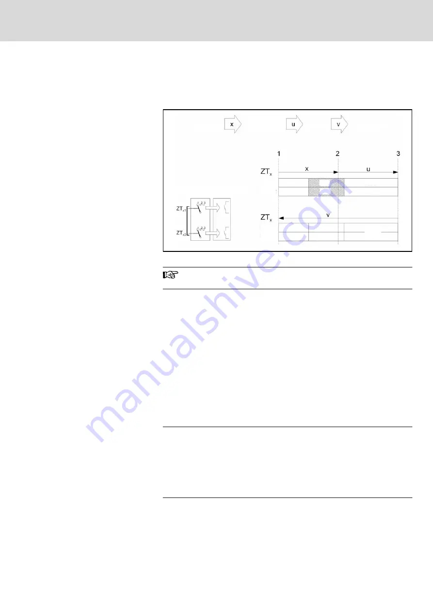
Panic
The pushing of the actuating elements into the panic position is evaluated in a
way that the enabling position is skipped when the actuating elements are re‐
leased.
Freigabe-
taster
Auswerte-
Elektronik
Freigabe
home position
enabling
panic
home position
Enabling
switch
Evaluation
electronics
Circuit 1
Circuit 2
Circuit 1
Circuit 2
Circuit 1
Circuit 2
OFF
OFF
OFF
OFF
ON
ON
OFF
OFF
OFF
OFF
OFF
OFF
Fig.7-11:
Contact travel diagram for panic
At the IndraControl VCH 08.1 devices, the enabling buttons always
feature 2 circuits.
To meet the safety category 3 PL d in accordance with EN ISO 13849-1, the
enabling switch must be realized with 2 circuits and these circuits have to be
monitored on short circuits.
The safety category 3 PL d means, that 1 failure must not lead to the loss of
the safety function, and whenever possible, the single failure is detected.
The connection example in
fig. 7-22 "Connection example with PILZ PNOZ s6.1
shows how the safety category 3 PL d can be
fulfilled by the enabling switch up to the output terminal K4 within the connection
module. Observe that the entire concept of the machine must be laid out ac‐
cording to the above mentioned principles.
The monitoring of the simultaneity by the monitoring device is necessary, be‐
cause otherwise maybe a failure culmination would not be recognised and this
would cause the safety loss.
Example:
Example
If one channel of the enabling button switches to the enabled state as a result
of a failure and after some time the second channel also switches to the enabled
state as a result of an failure, then no de-energisation by the enabling button
would be possible. Further the EN 60204-1 specifies that the enabling button
is to be connected to a category 0 stop or a category 1 stop, i.e. the energy
must be switched off.
For calculating the PL for the "enabling" safety function the PL and B10d values
of all involved components have to be included. For details for calculating the
PL for the whole safety function see EN ISO 13849-1 (chapter 6.3, appendix H
and appendix I).
DOK-SUPPL*-VCH*08.1***-PR02-EN-P
Rexroth IndraControl VCH 08.1 Hand-held Terminal
Bosch Rexroth AG
75/117
Pin Assignments of the IndraControl VCH 08.1
Содержание Rexroth VCH 08.1
Страница 1: ...Electric Drives and Controls Pneumatics Service Linear Motion and Assembly Technologies Hydraulics ...
Страница 12: ...Bosch Rexroth AG DOK SUPPL VCH 08 1 PR02 EN P Rexroth IndraControl VCH 08 1 Hand held Terminal 10 117 ...
Страница 28: ...Bosch Rexroth AG DOK SUPPL VCH 08 1 PR02 EN P Rexroth IndraControl VCH 08 1 Hand held Terminal 26 117 ...
Страница 60: ...Bosch Rexroth AG DOK SUPPL VCH 08 1 PR02 EN P Rexroth IndraControl VCH 08 1 Hand held Terminal 58 117 ...
Страница 92: ...Bosch Rexroth AG DOK SUPPL VCH 08 1 PR02 EN P Rexroth IndraControl VCH 08 1 Hand held Terminal 90 117 ...
Страница 114: ...Bosch Rexroth AG DOK SUPPL VCH 08 1 PR02 EN P Rexroth IndraControl VCH 08 1 Hand held Terminal 112 117 ...
Страница 118: ...Bosch Rexroth AG DOK SUPPL VCH 08 1 PR02 EN P Rexroth IndraControl VCH 08 1 Hand held Terminal 116 117 ...
Страница 119: ...Notes DOK SUPPL VCH 08 1 PR02 EN P Rexroth IndraControl VCH 08 1 Hand held Terminal Bosch Rexroth AG 117 117 ...


