RE 30011-B, Edition 10.2021, Bosch Rexroth AG
Mounting |
Pressure and flow control system SYDFE1 series 2X, 3X
49/96
NOTICE
Insufficient suction pressure!
Risk of damage! Generally, a minimum permissible suction pressure at port “S” is
prescribed for SYDFE1 control systems in all installation positions. If the pressure
at port “S” drops below the specified values, damage may occur which can lead
to the destruction of the SYDFE1 control system.
▶ Make sure that the required suction pressure is achieved.
This is influenced by:
– appropriate piping of the suction cross-sections
– appropriate pipe diameters
– appropriate position of the tank
– appropriate viscosity of the hydraulic fluid
The machine or system manufacturer is responsible for dimensioning the lines.
The SYDFE1 control system must be connected to the rest of the hydraulic
system in accordance with the hydraulic circuit diagram of the machine or system
manufacturer.
Connect exclusively hydraulic lines to the service and function ports.
▶ Always ensure absolute cleanliness.
▶ Install the SYDFE1 control system in a clean condition.
▶ Make sure that all ports, hydraulic lines and add-on units (e.g. measuring
devices) are clean.
▶ Make sure that no contaminants can enter the system, also while you are
closing the ports.
Observe the following notes when routing suction, pressure and case drain
lines.
▶ See to it that the suction line (pipe or flexible hose) is as short and straight as
possible.
▶ The line cross-section of the suction line is to be dimensioned so that the
pressure in the suction port does not fall below the minimum permissible value
and the maximum permissible pressure is not exceeded.
▶ Observe air tightness of the junctions and pressure resistance of the hose, also
with respect to the atmospheric pressure.
▶ In conjunction with the pressure lines, make certain that the pipes, hoses and
connecting elements are approved for the operating pressure range.
▶ Always route case drain lines so that the housing is constantly filled with
hydraulic fluid and ensure that no air gets through the shaft seal ring even
during extended standstill periods. Under no operating conditions may the
pressure inside the case exceed the limit values specified for the SYDFE1
control system in the data sheet. The case drain line in the tank must in any
case end up below the minimum fluid level (see chapter 7.3 “Installation
positions and piping of SYDFE1 systems“, page 43).
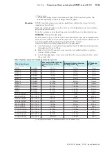
The ports and mounting threads are rated for the operating pressures specified
in the data sheet. The machine or system manufacturer must ensure that the
connecting elements and lines comply with the specified operating conditions
(pressure, flow, hydraulic fluid, temperature) with the necessary safety factors.


