


3 609 929 408/2.1 | LTH
Electric Drives and Controls
| Bosch Rexroth AG
41/60
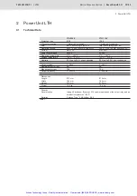
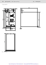
2 Power Unit LTH
2.6
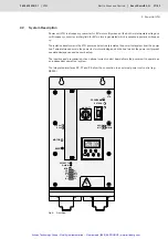
Connection and Start-Up
Customized cabling for power line, hand-held power tools and interfaces are available from the manufac-
turer. These connections are located on the lower side of the power unit (fig. 8).
When connecting the power unit, the following order should be observed:
1 Insert interface cable and secure with bolts
2 Insert Amphenol connector for hand-held power tool and turn locking ring until it locks in place.
WARNING:
The safety measure “isolation by transformer” is used by the power unit. For this reason, no
potential equalization conductor (PE) must be connected to the hand-held power tool.
3 Insert power line cable with IEC plug and clamp with wire loops.
CAUTION:
The specified power line voltages for the power unit used must be complied with. The values
are shown in the technical data.
4 Switch on power unit with main switch which is mounted on lower side of power unit.
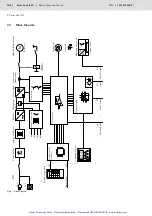
After switching on, a hardware self-test is performed. The readiness for operation is signalled by LED
“BTB,” possible system errors are indicated by the appropriate LEDs on the front panel.
NOTE:
When operating the power unit with a stock control, it must be connected to user interface
X13.
WARNING:
Equipment connected to interfaces X2, X7, X8, X10 and X11 of the power unit must comply
with the regulations of class of protection “protective low voltage”. The usern interface X13
is optically decoupled.
☞
Artisan Technology Group - Quality Instrumentation ... Guaranteed | (888) 88-SOURCE | www.artisantg.com