background image

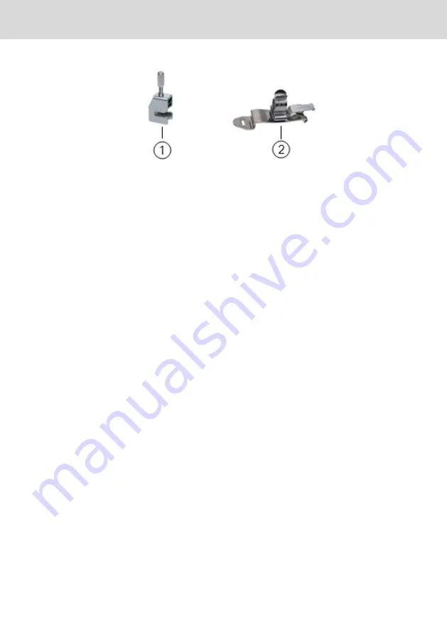
Vendor: Ikotec

Vendor: Phoenix Contact

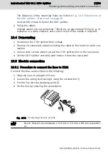
Fig.  10-13:   Shielding clamps

11  Commissioning

The product can be used directly. No configuration is required.

12  Device description

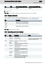
Two operator displays can be connected to one PC using a CDI+ splitter. All op-

erator displays show the same screen. The operation depends on the wiring of

the inputs "SEL" and "MOD".

IndraControl VAC 08.1 CDI+ Splitter 

23/33

Device description

R911400465_Edition 01 Bosch Rexroth AG

Содержание rexroth IndraControl VAC 08.1

Страница 1: ...IndraControl VAC 08 1 CDI Splitter Operating Instructions R911400465 Edition 01 ...

Страница 2: ...applications for industrial property rights Liability The specified data is intended for product description purposes only and shall not be deemed to be a guaranteed characteristic unless expressly stipulated in the contract All rights are reserved with respect to the content of this documen tation and the availability of the product Editorial Department Development Automation Systems Control Hard...

Страница 3: ...mbol 4 3 3 Symbols used 5 3 4 Explaining the signal alert symbol on the device 5 4 Intended use 5 5 Accessories 6 5 1 External 24 V power supply unit 6 5 2 Connecting cables for the USB interface 6 5 3 Adapter cable from the display port to the HDMI 6 5 4 Connecting cables for the CDI interface 6 6 Ambient conditions 7 7 Standards 9 7 1 CE marking 9 7 1 1 Declaration of conformity 9 7 2 UL CSA cer...

Страница 4: ... 10 5 6 Connecting the USB interface to the PC 19 10 5 7 Connecting the image interface to the PC 19 10 6 Overall connection diagram 19 10 7 Mounting recommendation for CDI cables with long lengths in an interference prone environment 20 10 7 1 Cables routing 20 10 7 2 Potential equalization 20 10 7 3 Shielding 20 10 7 4 Additional shielding connection in case of strong electrical interfer ences a...

Страница 5: ... 15 1 Accessories and spare parts 27 15 2 Type code 27 16 Disposal 28 16 1 Return 28 16 2 Packaging 29 17 Service and support 29 Index 31 IndraControl VAC 08 1 CDI Splitter III Table of Contents R911400465_Edition 01 Bosch Rexroth AG ...

Страница 6: ...IV IndraControl VAC 08 1 CDI Splitter Bosch Rexroth AG R911400465_Edition 01 ...

Страница 7: ...ring Commissioning Operation Decommissioning Product phases Target groups Activities Design engineer Programmer Technologist Process specialist Select Prepare Design Construct Mechanic electrician Unpack Mount Install Programmer Commissioning engineer Parameterize Program Configure Simulate Technologist Process specialist Optimize Test Machine operator Maintenance technician Service Operate Mainta...

Страница 8: ... to chapter 2 1 Product identification on page 3 1 4 Related documents Title Part number and document type Rexroth IndraControl VAP 01 Power Supply Unit R911339613 Operating Instructions Rexroth IndraControl VPB 40 4 Control Cabinet PC R911376309 Operating Instructions Rexroth IndraControl PR4 and VR4 Control Cabinet PC R911384699 Operating Instructions Rexroth IndraControl VDP 16 3 40 3 60 3 Oper...

Страница 9: ...y UN AC 230V 115V IN 2 7A 5A MNR R911171065 GA1 TYP VAP01 1H W23 024 010 NN Bosch Rexroth Electric Drives and Controls GmbH D 64711 Erbach SN 004012652 7261 IND CONT EQ 18WM I C B H T V FD 11W40 1 2 3 4 8 9 5 10 6 12 11 13 15 DC 24V 10 3A 14 I Made in Germany 1 Word mark 2 Division or plant number 3 Type name type code 4 Part number 5 State of revision 6 Date of manufacture yyWww 7 Nominal voltage...

Страница 10: ...ANSI Z535 6 2006 The signal word draws attention to the safety instruction and indicates the risk potential The safety alert symbol triangular safety reflector with exclamation marks preceding the signal words Danger Warning Caution indicates hazards for persons DANGER In case of non compliance with this safety instruction death or serious injury will occur WARNING In case of non compliance with t...

Страница 11: ... monitor interface Risk of damaging the device if not expressly sta ted accessories mounting parts and other com ponents cables and lines are used NOTICE The CDI splitter may be used only as intended and with the accessories mounting parts and other components specified in this documentation Compo nents that are not expressly mentioned must neither be attached nor connected The same applies to cab...

Страница 12: ...m RKB0019 003 0 R911171167 Length 3 m Tab 5 2 Ordering data of the connecting cables for the USB interface 5 3 Adapter cable from the display port to the HDMI Ordering code Part number Description VAC07 1SAA DPN HDM 01 0 R911399838 Length 1 m Adapter cables active display port to HDMI to connect VAC 08 and PR VR VAC07 1SAN DPN HDM 01 0 R911399986 Length 1 m Adapter cables passive display port to H...

Страница 13: ...ient temperature 5 C to 45 C 20 C to 60 C 20 C to 60 C Maximum temperature gradient Temporal temperature changes up to 3 C per minute Temporal temperature changes up to 3 C per minute Temporal temperature changes up to 3 C per minute Relative humidity Climatic class 3K3 acc to EN 60721 condens ing not allowed Max 80 air humidity at 25 C Climatic class 3K3 acc to EN 60721 condens ing not allowed Ma...

Страница 14: ...ctions NOTICE Due to the risk of corrosion avoid sulphurous gases e g sulphur dioxide SO2 and hydrogen suphide H2S The product is not resistant against these gases Failure of the product due to contaminated air NOTICE The ambient air must not contain acids alkaline solutions corrosive agents salts metal vapors and other electrically conductive contaminants in high concentrations The devices to be ...

Страница 15: ...ormity The electronic products described in the present operating instructions comply with the requirements and the target of the following EU directive and with the following harmonized European standards EMC directive 2004 108 EC The electronic products described in the present operating instructions are in tended for use in industrial environments and comply with the following require ments Sta...

Страница 16: ...nd CSA marking applies only to the device upon delivery After modifying the device verify the UL and the CSA conformity 8 Technical data Degree of protection IP 20 Weight 0 54 kg Tab 8 1 Degree of protection and weight 8 1 Voltage supply Nominal input voltage 24 V DC use a 24 V power supply unit acc to DIN EN 60742 classification VDE 0551 for example the power supply unit VAP01 1H W23 024 010 NN p...

Страница 17: ...Nominal value at 0 Nominal value at 1 3 V to 15 V 18 V to 30 V Input current Nominal value at 0 Nominal value at 1 2 5 mA 2 8 mA to 6 mA Cable length unshielded 100 m Short circuit protection overcurrent protection Typ 0 6 A Tab 8 3 Characteristic values of the digital 24 V inputs SEL and MOD IndraControl VAC 08 1 CDI Splitter 11 33 Technical data R911400465_Edition 01 Bosch Rexroth AG ...

Страница 18: ...gital 24 V inputs Phönix connector strip 5 pin MC1 5 5 G 3 5THT1 Phönix socket strip 5 pin FK MCP 1 5 5 ST 3 5 XUSB USB 2 0 connection to the PC USB socket Type A USB plug Type A XHDMI HDMI HDMI female connector HDMI connector XCDI tx1 CDI interface to the first operator display RJ45 socket RJ45 plug 12 33 Interfaces IndraControl VAC 08 1 CDI Splitter Bosch Rexroth AG R911400465_Edition 01 ...

Страница 19: ...on 1 24 24 V supply voltage 2 24 0 V supply voltage 3 MOD SEL 0 V for switching and MOD 4 SEL 24 V switching input 5 MOD Enables the operation at both oper ator displays or at no operator dis play Tab 9 2 Pin assignment X1S1 For the function on the digital inputs refer to chapter 12 1 Func tion of the digital inputs on page 24 Operating the operator display as well as the USB data traffic only pos...

Страница 20: ...ection to operator display 1 XCDI tx2 CDI connection to operator display 2 Tab 9 3 Interfaces ordering information on the cables refer to chapter 5 Accessories on page 6 10 Mounting demounting and electric installation 10 1 Installation notes The CDI splitter is intended for the rear panel mounting Fig 10 1 Permitted mounting position The LED displays may not be hidden Provide the following minimu...

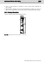
Страница 21: ...e cables e g motor ca bles when routing HDMI USB and CDI cables Avoid parallel cable routing 10 2 Housing dimensions The CDI splitter has the following dimensions Fig 10 2 Dimensions of the CDI splitter Front view IndraControl VAC 08 1 CDI Splitter 15 33 Mounting demounting and electric installation R911400465_Edition 01 Bosch Rexroth AG ...

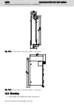
Страница 22: ...Rear view Fig 10 4 Dimensions of the CDI splitter Side view 10 3 Mounting 1 Mounting CDI splitter to the rear panel 16 33 Mounting demounting and electric installation IndraControl VAC 08 1 CDI Splitter Bosch Rexroth AG R911400465_Edition 01 ...

Страница 23: ...h screws used to attach the CDI splitter box to the rear panel 4 Lift the CDI splitter vertically and remove it from the rear panel 10 5 Electric connection 10 5 1 Procedure to connect the lines to X1S1 Connect the lines as described in the following 1 Strip the lines to a length of 9 mm 2 Loosen the spring by pressing it using the screwdriver 3 Put the line into the clamping point 4 Fix the line ...

Страница 24: ... W23 024 010 NN see chap ter 5 1 External 24 V power supply unit on page 6 For further information on the external power supply unit and on the creation of overvoltage categories re fer to the documentation of the power supply unit All lines of the 24 V voltage supply have to be routed separately from lines carry ing higher voltages Destruction of the CDI splitter due to connec tion under voltage ...

Страница 25: ... 10 5 6 Connecting the USB interface to the PC Connect the XUSB connection to a USB port of the PC using a USB cable The maximum cable length is 3 m Use this connection to set up the USB connection between the operator display and the PC 10 5 7 Connecting the image interface to the PC Connect the XHDMI connection to the PC using an adapter cable The maxi mum cable length is 3 m This connection is ...

Страница 26: ...verters Mechanical protection against tensile load and compressive load on the ca bles Comply with the permissible bending and torsional stress of the cable Avoid dirt at the R45 plug which can occur while drawing in the cables in the system 10 7 2 Potential equalization Ensure that no compensating current flows via the cable shield of the CDI ca bles between device and machine parts during the in...

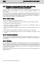
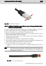
Страница 27: ...mped when connecting the shielding to the equipotential bonding Avoid mechanical stress tensile compressive on the plug Use an EMC shielding clamp suitable for the cable diameter Crimping of the cable impairs the electrical properties of the CDI cable To mount the shielding connection proceed as follows 1 Only remove the CDI cable jacket on the length required for the connec tion The CDI cable is ...

Страница 28: ...e foil shield is usually plastic coated on one side for an improved stability The plastic coating is insulating Fig 10 10 Foil shield of the CDI cable Fig 10 11 Foil shield removed 3 Fasten cable with EMC shielding clamp Fig 10 12 CDI cable with shielding clamp More shielding clamps 22 33 Mounting demounting and electric installation IndraControl VAC 08 1 CDI Splitter Bosch Rexroth AG R911400465_E...

Страница 29: ...onfiguration is required 12 Device description Two operator displays can be connected to one PC using a CDI splitter All op erator displays show the same screen The operation depends on the wiring of the inputs SEL and MOD IndraControl VAC 08 1 CDI Splitter 23 33 Device description R911400465_Edition 01 Bosch Rexroth AG ...

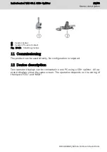
Страница 30: ... LED for status display of the first con nected operator display Operating state operator display 2 CDI interface to the second operator display LED for status display of the second connected operator display Functional earth Fig 12 1 Connector panel of the CDI splitter 12 1 Function of the digital inputs SEL MOD Operator display 1 XCDI tx1 Operator display 2 XCDI tx1 0 0 Active 1 0 Active 24 33 D...

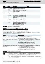
Страница 31: ... the following table if one of the LEDs is on LED Name Description Action VIN LED is on Normal mode LED is off 24 V DC missing Check the cable of the voltage supply which is connected to X1S1 Video1 LED flashing green Image data is sent to the operator display 1 LED off The PC does not sent any image data to the CDI splitter Link1 LED green Communication active und operator panel selected LED red ...

Страница 32: ...page 12 Errors Troubleshooting The LED VIN is not on at the CDI splitter Connector not connected to X1S1 External voltage supply does not supply voltage The active operator display cannot be operated Check whether all cables are plugged in control cabinet PC operator display and CDI splitter Check for the plug X1S1 at the input SEL Check for the plug X1S1 at the input MOD No image is displayed at ...

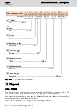
Страница 33: ...free Check all plug and terminal connections of the components for proper tight ness and possible damage at least once a year Check that no cables are broken or pinched Replace damaged parts immediately 15 Ordering information 15 1 Accessories and spare parts For ordering information on accessories and spare parts refer to chapter 5 Ac cessories on page 6 15 2 Type code The CDI splitter with CDI i...

Страница 34: ...er design Standard NNNN Fig 15 1 Type code of the CDI splitter 16 Disposal 16 1 Return For disposal our products can be returned free of charge However the prod ucts must be free from remains such as oil grease or other impurities Furthermore the products returned for disposal must not contain any undue for eign substances or external components Send the products free of charge to the following ad...

Страница 35: ... Service Hotline and Service Helpdesk under Phone 49 9352 40 5060 Fax 49 9352 18 4941 E mail service svc boschrexroth de Internet http www boschrexroth com Additional information on service repair e g delivery addresses and training can be found on our internet sites Service worldwide Outside Germany please contact your local service office first For hotline num bers refer to the sales office addr...

Страница 36: ...30 33 IndraControl VAC 08 1 CDI Splitter Bosch Rexroth AG R911400465_Edition 01 ...

Страница 37: ...Feedback 3 D Declaration of conformity 9 Degree of protection 10 Demounting 17 Device description 23 Digital 24 V inputs 13 Digital 24 V inputs SEL and MOD 11 Digital inputs 24 Display elements 25 Disposal 28 Documentation Change record 1 Documents related 2 E Electric connection 17 Electrical interferences 21 EMC interferences 20 EMC shielding clamp 22 Error causes 26 Error display 25 External 24...

Страница 38: ...4 Relative humidity 7 S Safety instructions 3 Scope of delivery 3 SEL 11 18 Service hotline 29 Shielding 20 Shielding CDI cable 20 Shieling clamps 22 Shock 8 Signal alert symbol 4 Signal words 4 Standards 9 Suggestions 3 Support 29 Switching input 13 Symbols 5 T Target groups 1 Technical data 10 24 V input 10 Degree of protection 10 Digital 24 V inputs SEL and MOD 11 Weight 10 Temperature gradient...

Страница 39: ...Notes IndraControl VAC 08 1 CDI Splitter 33 33 ...

Страница 40: ...lectric Drives and Controls P O Box 13 57 97803 Lohr Germany Bgm Dr Nebel Str 2 97816 Lohr Germany Phone 49 9352 18 0 Fax 49 9352 18 8400 www boschrexroth com electrics R911400465 R911400465 DOK SUPPL VAC 08 1 IT01 EN P ...

Отзывы: