background image

64/68 Appendix

Bosch Rexroth AG

, APAS assistant K1100-10i V01.00.00 - V01.00.99, 3 842 565 050/2019-11

10 Appendix

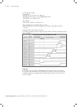
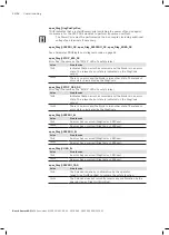
Has the submit interpreter StandaloneSPS.sub been implemented 
according to the risk assessment by the system integrator? Do 
error acknowledgment, drive release and movement release 
comply with the permissible safety specifications? 

Have error acknowledgment, drive release and movement release 
been implemented in the controller in accordance with the 
permissible safety specifications and has the function been tested? 

Checkliste funktionale Sicherheitsabnahme


I  di ser Checkliste sind Prüfpunkte angeführt, die in das Abnahmeprotokoll der Maschine 

miteinfließen können. Weitere in der Applikation vorhandenen Prüfpunkte müssen vom 

Systemintegrator ausgearbeitet und geprüft werden.


Diese Checkliste ist beispielhaft und muss applikationsspezifisch ergänzt werden. 

Bezeichnung:  

APAS assistant K1100-10i 

Version: 

V01.00.__ 

Maschinennummer: 

 ..................................................................... 

Seriennummer: 

 ..................................................................... 

Projektnummer: 

 ..................................................................... 

Bemerkung 

Kundensteuerung 

i.O.  n.i.O.  ntrag 

1.1  Betrieb ohne übergeordnete Steuerung 


1.2  Betrieb mit übergeordneter Steuerung 


Zusätzliche Schutzeinrichtungen 

i.O.  n.i.O.  ntrag 

2.1 


NOT-HALT 

i.O.  n.i.O.  ntrag 

3.1 

Lo le   OT-HALT NHL


3.2 


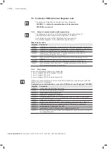
Checklist for functional safety acceptance

This checklist includes check items which can be included in the acceptance report for the 

machine. Further check items existing in the application must be developed and checked by 

the system integrator. This checklist is an example and must be amended as required for the 

application.
Designation:

Machine number: 

Serial number: 

Project number: 

Comment 

Customer controller 

OK  Not 

OK 

OK  Not 

OK 

OK  Not 

OK 

Operation without higher-level controller

Operation with higher-level controller

Additional protective devices 

Have all additional protective devices which have resulted from the 
risk assessment by the system integrator been installed and has 
their effectiveness been tested? 

EMERGENCY STOP 

Is the EMERGENCY STOP on the smartPAD (without automatic 
restart) effective? 

Ensure that the signal 

Local EMERGENCY STOP NHL

 is active 

on the secure output of the smartPAD (output byte 0, bit 0). 

Is the local EMERGENCY STOP (output signal at PLC-R) 
effective?

Ensure that the secure output signal is inactive on K911B in the 
safety module: first output signal OUT0 

Check if an error (channel 1 or channel 2) is detected 
(see further documentation IndraControl S20 Module with 
secure digital outputs S20-PSDO-8/3 (R911369166)). 

Entry 

Entry 

Entry 

Содержание Rexroth APAS assistant K1100-10i

Страница 1: ...Installation instructions 3 842 565 050 2019 11 Replaces ENGLISH APAS assistant K1100 10i V01 00 00 V01 00 99 3 842 562 910 ENGLISH ...

Страница 2: ...red product may thus vary from the illustration The original installation instructions are in German DE Die vorliegende Montageanleitung ist in den hier angebenen Sprachen verfügbar Weitere Sprachen auf Anfrage Als gedruckte Version oder als PDF Datei zum Download aus dem Medienverzeichnis www boschrexroth com medienverzeichnis Geben Sie in die Suchmaske oben rechts unter Suche 3 842 563 137 ein d...

Страница 3: ...ipment 13 2 6 Personal protective equipment 13 2 7 Integrator responsibilities 14 2 8 Owner responsibilities 14 2 9 General safety instructions 15 2 10 Product specific safety instructions 15 3 Product description 16 3 1 Scope of delivery 16 3 2 Product overview 17 3 3 Speed switch function optional 17 3 4 Safety functions 18 3 4 1 Approaching the robot arm 18 3 4 2 Discrete EMERGENCY STOP 19 3 4 ...

Страница 4: ... Removing the robot arm 38 5 1 2 Transporting the robot arm 39 5 1 3 Transporting the robot controller 40 5 2 Storing the product 41 6 Assembly and installation 42 6 1 Ambient conditions 42 6 2 Mechanical interface 42 6 2 1 Installing the robot arm 43 6 2 2 Installing the hose breakaway device 44 6 2 3 Installing the safety module 46 6 2 4 End effector interface 46 6 3 Electrical interfaces 47 7 C...

Страница 5: ...atic external operation 59 8 1 2 T1 operation 60 8 1 3 T2 operation 60 8 2 Decommissioning 60 8 3 Disposal 60 9 Servicing and repair 61 9 1 Maintenance instructions 61 9 2 Maintenance of robot arm 61 9 3 Maintenance of robot controller 62 9 4 Maintenance of safety module 63 9 5 Maintenance of hose breakaway device 63 10 Appendix 64 ENGLISH ...

Страница 6: ...ble at any time When selling the product this documentation must be handed on 1 2 Further documentation To be able to integrate the product into existing systems the following documentation must be available in addition to these installation instructions which you must read thoroughly and ensure you have understood it Title Version number Operating instructions KR C4 smallsize 2 KUKA Roboter GmbH ...

Страница 7: ...t as follows SIGNAL WORD Type and source of danger Consequences of non compliance f f Measures to prevent danger f f Warning sign points out the danger Signal word indicates the severity of the danger Type and source of danger indicates the type and source of the danger Consequences describes the consequences of non compliance Prevention states how the danger can be avoided Table 1 Types of risk a...

Страница 8: ...s a risk of injury Table 2 Meaning of the safety markings Symbol Meaning Hazard Dangerous electrical voltage Suspended load No unauthorized entry Use foot protection Observe instructions 1 3 3 Information symbols Table 3 Meaning of the information symbols Symbol Meaning If this information is not observed the product cannot be used and or operated as designed f f Single independent action 1 2 3 Nu...

Страница 9: ...opping distances Adjustment referencing Adjustment referencing is used to check if the current position of the robot and the additional axes matches a reference position KLI KUKA Line Interface Connection to higher level controller infrastructure PLC archiving KRC KUKA Robot Control m Mass of rated load and additional load on the arm Phi Rotation angle in around the respective axis POV Program ove...

Страница 10: ...wing intended use Independent performance of changing handling tasks with attached or gripped tools in assembly as well as support of the operator in monotonous repetitive tasks Installation on various substructures or in an existing system Use exclusively in industrial applications and indoors To prevent head and eye injuries movements of the APAS assistant with adapted end effector tool and grip...

Страница 11: ...AG is not liable for any personal injury or property damage resulting from improper use of the product For purchased parts and third party makes incorporated into the product see the manufacturer s instructions and the supplied documentation see Further documentation on page 6 of the respective manufacturers 2 4 Personnel qualifications The activities described in these installation instructions m...

Страница 12: ... skin maintenance and commissioning Professional training in a technical field Certificate of instruction in electrical engineering Due to his her training knowledge and experience the person commissioning the sensor skin is able to perform the following tasks Removal and installation of the sensor skin Integration of additional sensor elements e g optional collision detection element into the ove...

Страница 13: ...work schedules BCI SP AP038 Advanced course Integration into projects BCI SP AP037 You can find an overview of the current training courses and training content online at https www bosch apas com downloads 2 5 Installed safety equipment The APAS assistant has the following safety equipment Sensor skin on axis segments 1 5 of the APAS assistant Sensor skin on the rotary union Robot controller Safet...

Страница 14: ...echnical documentation operating and maintenance instructions vendor documentation etc for the owner and their personnel f f Inform the owner about tasks they must perform according to these installation instructions e g definition of any maintenance cycles not yet defined f f Attach the CE mark in a visible location on the system f f Instruct the personnel on any existing residual risks 2 8 Owner...

Страница 15: ...ducts should not be under the influence of alcohol drugs or medication that may affect their ability to respond Use only original accessories and spare parts from Rexroth in order to prevent hazards to people due to unsuitable spare parts Observe the technical data and ambient conditions specified in the product documentation 2 10 Product specific safety instructions Make sure that the EMERGENCY S...

Страница 16: ...on or object The typical switching distance is approx 50 mm As soon as the sensor range is free again the APAS assistant will automatically resume the motion sequence 3 1 Scope of delivery The following is included in the scope of delivery APAS assistant K1100 10i robot arm KUKA Agilus KR 10 R1100 2 with sensor skin and signal lamp Robot controller KUKA KR C4 smallsize 2 Safety module Cable sets s...

Страница 17: ...e APAS assistant is monitored by safety sensors installed by the customer If a person moves into the monitoring range of the safety sensors the permissible velocity is switched from speed velocity to collaboration velocity The robot delay is safely monitored It the robot does not reach the collaboration velocity within the expected time a safety stop 1 is triggered The collaboration speed is safel...

Страница 18: ...2 see Further documentation on page 6 Sections 3 4 1 to 3 4 3 list specific safety functions of the APAS assistant K1100 10i 3 4 1 Approaching the robot arm Safety function Achieved performance level PFHD 1 h Operator approaching the robot arm PL d 6 6E 7 The sensor skin is used to monitor the area around the robot arm Upon approaching the sensor skin typical triggering distance approx 50 mm the s...

Страница 19: ...000 cycles per channel corresponding to the typical component values for an EMERGENCY STOP system as per IEC 60947 and ISO 13850 Maximum demand rate 3840 cycles per year or MTTFd 260 4 a 3 4 3 Local EMERGENCY STOP Safety function Achieved performance level PFHD 1 h Local EMERGENCY STOP PL d 2E 7 A local emergency stop is triggered when the robot system signals a local emergency stop The safety fun...

Страница 20: ...PLC R 2 0 Safety option active PLC R KRC 0 0 Reserved 1 PLC R KRC 0 1 Input for external EMERGENCY STOP PLC R KRC 0 2 Operator protection sensor skin triggered PLC R KRC 0 4 Safety STOP 1 all axes PLC R KRC 0 5 Safety STOP 2 all axes PLC R KRC 1 0 US2 supply voltage PLC R KRC 1 1 Safe operating stop all axes PLC R KRC 1 2 Reserved 11 PLC R KRC 1 3 Reserved 12 PLC R KRC 1 4 Reserved 13 PLC R KRC 1 ...

Страница 21: ...ncy stop safe clock output channel 2 CLK CH2 K911B 0 PLC R CUSTOMER Local emergency stop on APAS assistant clock output channel 1 CLK CH1 K911B 1 PLC R CUSTOMER Local emergency stop on APAS assistant clock output channel 2 CLK CH2 PLC R KRC 0 1 Input for external EMERGENCY STOP 3 5 3 Incorporation of end effector EMERGENCY STOP into safety controller of APAS assistant Safety module BMK PIN Signal ...

Страница 22: ... no longer applies STOP 2 Switch off power via main switch or power failure STOP 0 Internal error in the part of the robot controller which is not safety related STOP 0 or STOP1 depending on cause of error Change operating mode during operation Safety stop 2 Open safety door operator protection Safety stop 1 Release enabling device Safety stop 2 Fully depress enabling device or error Safety stop 1...

Страница 23: ...s direction x and y Range 1 101 mm Repeat accuracy 0 03 mm Weight of mechanical equipment approx 60 kg Number of sensor elements two channel 108 basic 115 with sensor head option 122 with KEE option Upgrading to 192 Properties of the workpiece The workpiece must be suitable for collaborative operation i e no points cutting edges etc weight see Bearing load on page 25 Installation position stationa...

Страница 24: ... 4 1 2 Stopping distance and stopping times The max permissible collaboration velocity of 0 5 m s is set in the delivery state The system integrator must determine the stopping distance and the stopping times according to the current state of the art and adapt the collaboration velocity to the application The system integrator must prepare a risk assessment for this purpose To determine the stoppi...

Страница 25: ... 1 6 kg in total is 10 92 kg f f Observe the following parameters of the end effector for the calculation of the bearing load center of gravity f f For the calculation of the actual application specific bearing load use the KUKA specific program KUKALoad available for download at the website of KUKA Roboter GmbH f f Coordinate the actual bearing load with the manufacturer prior to commissioning th...

Страница 26: ...objects in the danger areas in front of the stated sensor element in order to minimize the risk of injury due to collision during rotation of axis 2 The following figures show the hazard area for two different angular positions of axis 3 during rotation of axis 2 as an example The actual danger area must be determined specifically for each application depending on the robot movement used 1 Stroke ...

Страница 27: ... does not detect the approach of objects to the application specific tool at the end effector unless the tool is equipped with an approved sensor skin extension 4 2 Robot controller data Property Value Dimensions W x H x D 615 mm x 580 mm x 540 mm Weight approx 60 kg Operating temperature 5 C to 45 C Storage temperature 25 C to 40 C Storage temperature without battery 25 C to 70 C Requirements for...

Страница 28: ...IP54 Standard length of connecting cable between robot arm and safety module see Connecting cables on page 30 Weight approx 20 kg Distance to adjacent objects min 200 mm Operating temperature 15 C to 35 C Storage temperature 40 C to 70 C Installation position Upright installation only see Installing the safety module on page 46 Requirements for the installation location see Ambient conditions on p...

Страница 29: ... function series TU1 S highly flexible PUR Using unsuitable hoses can lead to incorrect detection e g due to ESD Pneumatic hoses Manufacturer Diameter Color Article no Aventics ø 4 mm Blue R412009985 Aventics ø 4 mm Black R412009984 Aventics ø 6 mm Blue R412009988 Aventics ø 6 mm Black R412009987 Aventics ø 8 mm Blue R412009990 Aventics ø 8 mm Black R412009989 Clips Manufacturer Application Drawin...

Страница 30: ...erminal on robot controller M4 4 m 5 Sensor skin signal data cable between robot arm and safety module Robot arm XA1Safety module K741B X4 3 m 6 Customer installation Supply voltage 24 V Safety module F211 W801 and W101 7 Ethernet cable for communication between safety module and robot controller PROFIsafe Robot controller X66 Safety module K011 XF2 10 m 8 Handheld programming device cable Robot c...

Страница 31: ...Robot controller supply Robot controller X1 16 End effector interface Robot arm end effector X870 17 Customer 18 Supply DC 24 V customer 19 Handheld programming device 20 Robot controller 21 Robot base 22 Safety module 23 Customer controller 4 6 Bus topology PROFINET PROFIsafe 1 4 5 6 7 8 9 10 11 12 13 14 15 16 17 18 19 20 21 22 23 APAS assistant Steuerung Sicherheits steuerung Buskoppler mit Sich...

Страница 32: ...ment KR 10 R1100 2 APAS 400 V which has been developed for collaborative operation The catalog element must not be deleted 4 7 2 Safety controller The settings described below must be set accordingly in operation to ensure safe operation of the APAS assistant The max permissible collaboration velocity can only be actively reached with a rotational speed stop The rotational speed stop must not be d...

Страница 33: ...11 16 are reserved for the APAS assistant Monitoring space 14 EndStop The settings for monitoring space 14 EndStop include defined axis limits and the robot stops if they are exceeded This prevents damage due to APAS components on the robot colliding with each other The settings must be between the following limits Axis Lower limit Upper limit A1 170 170 A2 165 25 A3 45 135 A4 185 185 A5 90 100 A6...

Страница 34: ...S assistant must be monitored and the workspace must not be breached Upon commissioning the max velocity must be determined according to the instructions and the applicable standards and reduced if necessary The max velocity must be such that no collision with the sensor skin occurs and the biometric limits are not exceeded in case of a collision Axis monitoring The axis monitoring must be conside...

Страница 35: ...ationRoom Two monitoring spheres are active The first sphere 1 has been inserted into the center of the rotary union and must not be changed The second sphere 2 is intended for the end effector e g gripper on the rotary union and must be considered by the system integrator in the risk assessment Tools 2 16 are at the free disposal of the system integrator Ø 60 Ø 60 4 0 7 7 5 2 8 0 2 1 ENGLISH ...

Страница 36: ...End effector The load parametrization on the robot must be set by the system integrator in the application 4 7 4 Option packages The following option packages must have been placed in the WorkVisual project for operation of the APAS assistant Diagnosis Safety KUKA PROFINET MS LoadDataDetermination SafeOperation ...

Страница 37: ...ntroller The digital inputs outputs are transmitted via PROFINET and are connected to the following inputs and outputs of the KRC Signal direction KRC I O Variable names in KRC Short description PLC R KRC IN4220 apas_CustPLC_In1 Customer PLC R digital input 1 PLC R KRC IN4221 apas_CustPLC_In2 Customer PLC R digital input 2 PLC R KRC IN4222 apas_CustPLC_In3 Customer PLC R digital input 3 PLC R KRC ...

Страница 38: ...unloaded and transported by a specialist company or by trained personnel instructed on the safety technology 5 1 1 Removing the robot arm Removing the robot arm from the transport pallet f f Secure the robot arm against tipping f f Remove the nuts from the four screw connections 1 between the robot arm and the transport pallet Removing the robot arm from the installation surface f f Secure the rob...

Страница 39: ...fastening the robot arm can tip and cause life threatening injuries f f Make sure that the instructions for transport of the robot arm are adhered to NOTICE Risk of damage If force is applied to the sensor skin the sensor system can be damaged f f Lifting the robot arm at the sensor skin is not permitted Only light guiding is permitted f f The sensor skin must not be pinched by lifting gear f f Se...

Страница 40: ...lly above the robot 3 Attach four fastening ropes of equal length to the four ring screws 3 on the two holding plates The fastening ropes must be at least 1 500 mm long When attaching the fastening ropes make sure that there is no collision with the sensor skin 4 Stretch the fastening ropes so that they do not sag Neither should there be any traction There is a risk of the shipping pallet shifting...

Страница 41: ...uring storage see Ambient conditions on page 42 f f Cover the product completely in order to prevent contamination and dust deposits f f Clean the product and apply an acid free oil film to bare metal parts for protection against corrosion f f Set the product down on a flat level surface and secure the product against tipping rolling away or unauthorized use f f The product must be stored packaged...

Страница 42: ...pected limits No condensation or precipitation is permitted The product must be protected against damaging quantities of splashing water and dust The required space including free spaces and escape routes has been defined by the owner and has been inspected by the owner s safety officer prior to the production release The suitability of the environment must be assessed in an application specific r...

Страница 43: ... damage to the sensor system and robot arm f f Please note that tightly gripping and pressing the sensor skin during lifting and transport of the robot arm is not permitted Only light guiding is permitted f f Set down the robot arm only at the prepared installation location Otherwise there is a risk of tipping and damage f f Make sure that the installation location for the robot arm meets the foll...

Страница 44: ...astening screws with a tightening torque of 86 Nm 7 Remove the transport device 8 Connect the connecting cables to the customer control cabinet and the robot controller at the robot base and lock the connections 6 2 2 Installing the hose breakaway device Use only approved material for the hose breakaway device in order to ensure proper function see Hose breakaway device on page 29 Fastening the ho...

Страница 45: ...Insert the pneumatic lines 1 with hose fittings 2 or the pneumatic line into the hose mounting clips 3 When using hose fittings make sure that they are flush with the outer edges of the hose mounting clip 2 Close the hose mounting clips 3 in such a way that they click into place audibly 3 Repeat the previous steps to fasten the pneumatic lines to all hose mounting clips 4 In the pivot and rotation...

Страница 46: ...tion surface in vertical position upright according to the figure above 2 Fasten the safety module according to the information provided in the vendor documentation of RITTAL GmbH Co 6 2 4 End effector interface Observe the technical drawing for the mechanical interface of the end effector and the rotor component in the appendix Installing the end effector 1 Place the application specific end effe...

Страница 47: ...odule The connection of PE and 0V must be disconnected in the safety module and ensured in the customer control cabinet prior to commissioning The dielectric strength of the isolation of cables placed outside of the installation spaces complies with EN 60204 1 4 16 Cable placement according to EN 60204 1 The sensor skin cable must be placed at a distance of at least 0 5 m to the KUKA drive cables ...

Страница 48: ... is the participation in the advanced course Sensor skin maintenance BCI SP AP015 by the BCI Training Center or personal instruction recognized as equivalent by the manufacturer Application specific parametrization of the sensor skin is performed with the diagnosis software Sensorskin Monitor V1 3 2 0 or higher A profile in the diagnosis software with the correct total number of sensor elements mu...

Страница 49: ...terpreter Observe the information in the vendor documentation installation and operating instructions KSS 8 5 SI V6 Configuration of kinematics of KUKA Roboter GmbH f f Add the included program StandaloneSPS sub to the submit interpreter of the controller and start it When using the program StandaloneSPS the automatic operating mode must not be selected 7 3 2 Preparing the I O circuitry f f Connec...

Страница 50: ...rogram apas_Sequencer_Go TRUE 7 3 4 Starting the program Requirements for program start No program selected Operating mode T1 Brake test performed or integrated into program Adjustment referencing performed or integrated into program Procedure 1 Select the prepared program in the navigator 2 Carry out the SAK run 3 Switch to Automatic External operating mode The robot starts the programmed movemen...

Страница 51: ...PAS controller overwrites the variables DRIVES_ON CONF_MESS and EXT_START according to the automatic external interface description in the KUKA instructions in order to start an automatic restart as soon as there is no object near the sensor skin For this the following handshakes are performed 1 Switching on the drives Requirements USER SAF Sensor skin is not triggered ALARM STOP There is no activ...

Страница 52: ...canceled Automatic restart of the APAS controller The following diagram shows the signal routing between the APAS controller and the robot controller On item 2 To implement a restart after an EMERGENCY STOP the customer must integrate at least the variables DRIVES_ON CONF_MESS and EXT_START into the system controller These are connected with the safety module in the I O circuitry of the KR C4 cont...

Страница 53: ...s FALSE Depending on the function this input can be used for different purposes Reset of the state machine and coupled error and state messages as displayed via DiagCode after the cause of the error has been remedied This reset behavior is designed as an error reset Manual reset of a restart lock by the operator This reset is designed as a functional reset This function is only active in case of a...

Страница 54: ...p End effector EMERGENCY STOP apas_EndEff_EStop PLC R KRC IN4121 apas_CustPLC_InEStop Customer EMERGENCY STOP input signal apas_CustPLC_InEStop PLC R KRC IN4122 apas_CustPLC_OutEStop Customer EMERGENCY STOP output signal apas_CustPLC_OutEStop PLC R KRC IN4124 IN4139 apas_Diag_S20PSDI_DC APAS diagnosis code for safety card K911A in the safety module PLC R KRC IN4124 IN4139 apas_Diag_S20PSDI_DC APAS...

Страница 55: ...KRC IN4252 IN4259 apas_Diag_ SlotNo APAS diagnosis signal apas_Diag_SlotNo PLC R KRC IN4260 IN4267 apas_Diag_ SafetyIoNo APAS diagnosis signal apas_Diag_SafetyIoNo PLC R KRC IN4268 IN4275 apas_Diag_ SafetyChNo APAS diagnosis signal apas_Diag_SafetyChNo 7 5 2 Displayed statuses apas_Diag_SlotNo The diagnosis variable of the type BYTE indicates the slot reporting the diagnosis and or the S20 module ...

Страница 56: ...ate is indicated by the DiagCode apas_Diag_ESTOP_DSS_DC Error flag the same as the K1 K2 LED of a safety relay Value State device TRUE Indicates that an error has occurred and the block is in an error state The relevant error state is indicated on the DiagCode output FALSE There is no error and the block is in another state The relevant error state is indicated by the DiagCode apas_Diag_S20PSDI_Er...

Страница 57: ...diagnosis signal indicates the local EMERGENCY STOP on the APAS assistant apas_EndEff_EStop The diagnosis signal indicates the EMERGENCY STOP on the end effector apas_SensorSkin_Error The diagnosis signal indicates an error message of the sensor skin The APAS assistant is stopped Restarting is only possible after the cause of the error has been determined and remedied apas_SensorSkin_Go The diagno...

Страница 58: ...ange Await Device Ack Awaiting the response of the F device 16 8007 Data exchange Check Device Ack Checking the response of the F device CRC consecutive number F device error 7 6 2 Error states Errors are assigned to three error categories 1 Error category 16 C0XX highest priority 2 Error category 16 C1XX 3 Error category 16 C2XX lowest priority If there are two simultaneous errors in the PROFIsaf...

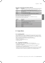
Страница 59: ...e activated FV activated Bit 5 Not used Bit 6 Not used Bit 7 Not used 8 Operation 8 1 Operating modes It is recommended to set up the following operating modes which can be selected after switching on the controller In addition the standard robot programs must be adapted to the specific application and integrated into the corresponding operating mode The standard robot programs include among other...

Страница 60: ...is intended for the following manual setup work Test run of new workflows Test run of changed workflows 8 2 Decommissioning DANGER Danger to life due to electric current and other energy sources For dismantling isolations and protective devices are disabled f f Make sure that the product is only dismantled by specialist personnel and in compliance with the local safety regulations f f Disconnect t...

Страница 61: ... work Cleaning agents Notice Interval Check state of sensor skin f f Perform a visual inspection If you find any damage or wear f f Contact the APAS service Daily Check state of robot arm and sensor skin f f Perform a visual inspection If you find any damage or wear f f Contact the APAS service Daily Verify tightening torque for sleeve nuts and fastening screws f f Observe the vendor documentation...

Страница 62: ...e of robot controller Maintenance work Cleaning agents Notice Interval Clean protective grille of exterior fan with a brush f f Observe the vendor documentation of KUKA Roboter GmbH At least yearly Verify function of relay outputs Yearly Cyclic functional test of operator protection and external EMERGENCY STOP devices Yearly Clean cooling ribs of drives with a brush At least every two years Clean ...

Страница 63: ...pection according to the inspection instruction Sensor skin safety circuits Version V01 02 01 or higher Yearly and following all modification work Replace filter inserts on fan f f Observe the vendor documentation of RITTAL GmbH Co KG To be defined by the operator Replace fan f f Observe the vendor documentation of RITTAL GmbH Co KG To be defined by the operator 9 5 Maintenance of hose breakaway d...

Страница 64: ... O n i O ntrag 2 1 3 NOT HALT i O n i O ntrag 3 1 Lo le OT HALT NHL 3 2 Checklist for functional safety acceptance This checklist includes check items which can be included in the acceptance report for the machine Further check items existing in the application must be developed and checked by the system integrator This checklist is an example and must be amended as required for the application De...

Страница 65: ...ive on the smartPAD secure input signal for external EMERGENCY STOP NHE input byte 0 bit 1 Check if an error channel 1 or channel 2 is detected see application description IndraControl S20 Module with secure digital inputs S20 PSDI 8 4 R911369170 Option Is the EMERGENCY STOP end effector PLC R without automatic restart effective Ensure that the input for external EMERGENCY STOP is active on the sm...

Страница 66: ...col_MachineNumber_Date_sig pdf FunctionalTest_MachineNumber_Date_sig pdf Robot KR C4 File safety configuration and robot project specific to the device Checksum of safety configuration Is the rotational speed stop enabled Have the safety configurations of monitoring spaces 14 to 16 remained unchanged and do they correspond to the delivery status of the manufacturer Permissible exception The maximu...

Страница 67: ...the values required in the application Have the additional loads been set to the values required in the application Have the passwords been changed prior to delivery User Operator Expert Person performing safety maintenance Person performing safety commissioning Administrator The passwords may only be handed over to customer personnel authorized for the application Disclosure on the customer side ...

Страница 68: ...Bosch Rexroth AG Postfach 30 02 07 70442 Stuttgart Germany Fax 49 711 811 7777 info boschrexroth de www boschrexroth com Subject to modifications 3 842 565 050 2019 11 ...

Отзывы: