background image

F 002 DG9 A00

2013-04-16

Bosch Limited

�6  |  N�� ����  |  Maintenance

en

7.2.2 

Replacing the braided hose for outlet

1. 

Switch off the master switch of the NTI 1000.

Risk of injury due to pressure in the hoses

High pressure in the hoses might cause the 
hoses to fly apart and cause injury.


Ensure that the pressure of the nitrogen 
tank is less than 2 bar before replace-
ment. 


i

To reduce the pressure, open the safety valve of the 
nitrogen tank till the pressure drops to atmospheric 
pressure. 


!

Ensure that you tighten the safety valve of the tank 
after releasing the pressure. If the safety valve is 
not tightened, the nitrogen filled into the tank will 
escape and the operating pressure of 10 bar will not 
be achieved.

2. 

Disconnect the braided hose from the quick 
coupler at the digital port for inflation/deflation 
(Fig. 2, Pos. 8, 10). 

3. 

Disconnect the male connector from the hose.

4. 

Disconnect the air filling connector. Refer to chapter 
7.2.1 for disconnecting the air filling connector.

5. 

Connect the male connector to the hose.

6. 

Connect the new hose to the quick coupler.

7. 

Complete the connection to the digital port. Ensure 
that the connection is leak proof.

8. 

Connect the air filling connector to the hose.

7.� 

Routine maintenance

7.�.� 

Draining the filter regulator of the N�� ����


!

Upon opening the drain of the FRC, mist will spur 
out. Ensure that you keep your eyes away while 
draining the FRC. 


Rotate the drain of the FRC till the mist is released. 
Close the drain when the mist is cleared.


i

Drain the FRC at least once every day.

7.�.2 

Changing the vacuum pump oil

Warning - risk of burns!

The hot surface of the vacuum pump can 
cause severe burns to the hands.


Allow the vacuum pump to cool before 
commencing maintenance work.


i

The vacuum pump oil needs to be topped up after 
every 60 hours of operation. Use order number  
F 002 DG6 401 to order vacuum pump oil.

1. 

Open the front door.

2. 

Observe the oil level through the sight glass of the 
vacuum pump. 


The oil should cover at least half of the sight 
glass. 


!

Inadequate vacuum pump oil will lead to dry running 
of the vacuum pump and to subsequent damage.

3. 

Turn off the master switch.

4. 

Place a container below the drain plug. 

5. 

Open the drain plug (Fig. 5, Pos. 2) on the vacuum 
pump and allow the oil to drain completely.

6. 

Close the drain plug and open the screw plug 
(Fig. 5, Pos. 1).

7. 

Add fresh vacuum pump oil.

8. 

Close the screw plug.

9. 

Close the front door.

Содержание NTI 1000

Страница 1: ...NTI 1000 en Original instructions Nitrogen tire inflator ...

Страница 2: ......

Страница 3: ...gen tank 8 4 2 Installation 9 4 2 1 Preparing to install the NTI 1000 9 4 2 2 Mounting the vacuum pump optional 9 4 2 3 Electrical connections 10 4 2 4 Pneumatic connections 10 4 3 Connecting the external nitrogen tank to the NTI 1000 11 4 4 Powering on the NTI 1000 11 4 4 1 Pressure sensor settings 11 4 5 Gas selection 12 4 5 1 Digital input 12 4 5 2 Direct input 12 5 Troubleshooting 13 6 Program...

Страница 4: ... pressurized equipment may be performed by persons with sufficient knowledge and experience in using pressurized devices and also be aware of the risks involved in the use of pressurized devices 2 2 Agreement Your use of the product means that you accept the fol lowing conditions Copyright Software and data are the property of Bosch Limited hereafter denoted as Bosch or its suppliers and are prote...

Страница 5: ...to perform any maintenance activity that is not described in this manual Inform Bosch before carrying out any repair or restoration Non compli ance invalidates the warranty R R In case air or nitrogen is not being delivered at any of the outlet valves when the NTI 1000 is powered on switch off the power supply and contact Bosch customer service R R In case of any emergency switch off the mains sup...

Страница 6: ...et F 002 DG3 A60 Tire valve connector F 002 DG3 A22 Male connector F 002 DG3 A54 Male connector G 1 4 F 002 DG3 A55 Hose clip F 002 DG3 A61 NTI 1000 original instructions F 002 DG9 A00 Power cable F 002 DG3 A31 Tab 1 Delivery specification i i The part numbers listed in table 1 are for reference only To order spare parts contact Bosch customer service 3 3 Special accessories Description Part numbe...

Страница 7: ...egulator Combination FRC where moisture oil and particulate matter are filtered Based on their molecular characteristics compressed gases have a tendency to adhere to solid surfaces known as adsorbents The process of compressed gases adhering to adsorbents is known as adsorption When the compressed air is passed through a tank with a Carbon Molecular Sieve CMS the molecules of oxygen are adsorbed ...

Страница 8: ...n The CMS tanks and nitrogen storage tank are firmly fixed and bolted to the cabinet 3 5 2 Filters for water and oil separation The input pneumatic line is connected to the Filter Reg ulator Combination FRC which acts as an input device and filtration device Air from the compressor at 10 bar is passed through the FRC where the moisture dirt and oil are filtered The collected moisture dirt or oil c...

Страница 9: ... door Fig 1 Pos 6 4 Clean the surface of the NTI 1000 cabinet with a weak solution of detergent using a soft cloth 4 2 2 Mounting the vacuum pump optional A00_5 1 3 4 2 Fig 4 Mounting the vacuum pump 1 Vacuum pump 2 Sight glass 3 Bracket 4 3 2 solenoid valve 1 Open the front door of the NTI 1000 2 Fasten the bracket Fig 4 Pos 3 to the cabinet 3 Fasten the vacuum pump Fig 4 Pos 1 to the bracket 4 F...

Страница 10: ... the power socket Fig 2 Pos 7 2 Connect the other end of the power cable to 230 VAC 3 phase mains supply The electrical connections are complete 4 2 4 Pneumatic connections i i Ensure that the compressor pressure is constantly at 10 bar i i Install a filter in the supply line from the compressor The filter should be able to function in the pressure range of 10 bar to 16 bar This is to ensure that ...

Страница 11: ...port Fig 2 Pos 5 of the NTI 1000 The connections to the external tank are complete 4 4 Powering on the NTI 1000 4 4 1 Pressure sensor settings 1 Switch on the compressor 2 Observe the pressure gauge Fig 7 Pos 3 of the FRC The pressure should be at least 10 bar i i If the pressure does not read 10 bar lift and rotate the knob Fig 7 Pos 1 in the clockwise direction till the pressure reaches 10 bar 3...

Страница 12: ...d gas air or nitrogen passes via the manifold Fig 3 Pos 2 and then to the vehicle tire The pressure is monitored by the pressure sensor and the value is displayed on the LCD 4 5 2 Direct input If the filling hose is connected to the direct port Fig 2 Pos 9 the selected gas air or nitrogen by passes the manifold Fig 3 Pos 2 Hence the pres sure is not monitored by the pressure sensor The tire pressu...

Страница 13: ...upply is not available because of any of the following reasons R R Power supply board has failed R R 5 VDC wire is disconnected from the terminal block R R LCD connector is disconnected from the con trol board R R Control board has failed R R Contact customer service to replace the power supply board R R Connect the 5 VDC wire back to termi nal block R R Connect the LCD connector to connec tor on ...

Страница 14: ...l 1 Select nitrogen or air inflation using the selector switch 2 In the main menu press 1 i i To change the unit between Bar or PSI press the UNIT key 3 Connect the filling nozzle to the tire 4 Press Enter Hold the filling nozzle to the tire until the set pres sure is reached After the set pressure is reached a long beep is heard and the red LED glows 5 Remove the filling nozzle and connect it to ...

Страница 15: ... the above procedure and adjust the position of the air filling connector 7 Maintenance Do not carry out any maintenance work that is not spe cifically recommended in this chapter Non compliance invalidates warranty 7 1 Spare and wearing parts Description Order number Filling nozzle F 002 DG1 A23 Braided hose for outlet F 002 DG1 A24 Vacuum pump oil F 002 DG6 401 Offered only for vacuum pump 7 2 R...

Страница 16: ... digital port Ensure that the connection is leak proof 8 Connect the air filling connector to the hose 7 3 Routine maintenance 7 3 1 Draining the filter regulator of the NTI 1000 Upon opening the drain of the FRC mist will spur out Ensure that you keep your eyes away while draining the FRC Rotate the drain of the FRC till the mist is released Close the drain when the mist is cleared i i Drain the ...

Страница 17: ...with the unit R R The NTI 1000 has to be transported in the original or equivalent packaging R R Heed the notes on initial commissioning R R Contact Bosch customer service to shift the NTI 1000 from one place to another R R During transportation fit transportation safeguards R R Ensure that there are no loose parts 8 2 Disposal and scrapping 8 2 1 Substances hazardous to water Oils and greases as ...

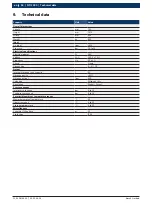
Страница 18: ...30 Voltage VAC 230 V 10 Frequency Hz 50 2 Phase Single Connection L N PE Output Internal Nitrogen tank capacity l 60 Nitrogen purity 95 Nitrogen output lpm 300 Selection Nitrogen Air Regulation Digital Direct Pressure gauges Inlet pressure gauge bar 0 to 16 Tank pressure gauge bar 0 to 16 Permissible ambient temperature ranges Maximum ambient temperature C 45 Operating range C 5 to 45 Storage temp...

Страница 19: ......
Страница 20: ...Bosch Limited P B No 3000 Hosur Road Bangalore 560 030 INDIA www boschindia com AADG Service in bosch com F 002 DG9 A00 2013 04 16 ...

Отзывы: