In addition, the machine elements to be driven must be secured axially via
the frontal centering hole.
Damage to property due to reversing mode!
NOTICE
Shaft damage! In case of intense reversing operation, the seat of the fitting
spring may deflect. Increasing deformations can lead to a break of shaft.
Preferably, use plain output shafts.
3.7
Bearing and shaft load
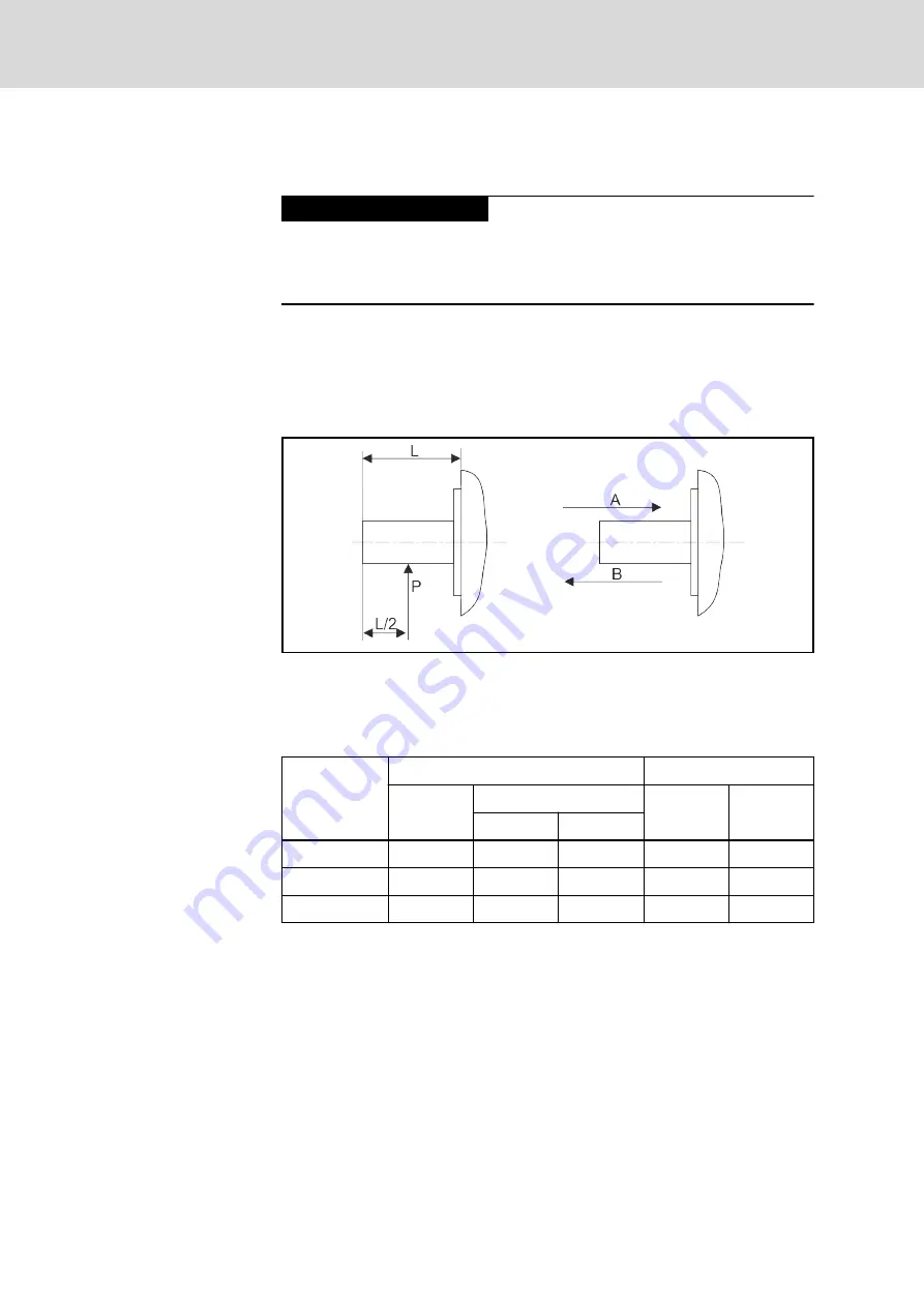
During operation, radial and axial forces act on the motor shaft and the motor
bearings. The design of the machine and the shaft-side mounting of drive ele‐
ments must be coordinated to ensure that the specified load limits are not ex‐
ceeded.
L
Shaft length
P
Point of application of radial force
A, B
Direction of axial force
Fig. 3-2:
Parameter for shaft load
The following table shows the allowed shaft load of single motors.
Motor
At assembly
During operation
Radial force
(N)
Axial force (N)
Radial force
(N)
Axial force
(N)
Direction A Direction B
MSM019
147
88
117.6
68.6
58.8
MSM031
392
147
196
245
98
MSM041
686
294
392
392
147
Tab. 3-4:
Allowed radial / axial force
In the case of adjusted point of application of radial force, calculate the al‐
lowed radial force according to the following formula.
Bosch Rexroth AG
DOK-MOTOR*-MSM********-DA05-EN-P
10/61
Synchronous Servomotors MSM
Operating conditions
Содержание MSM019A
Страница 1: ...Synchronous Servomotors MSM Data Sheet R911329338 Edition 05 ...
Страница 8: ...Bosch Rexroth AG DOK MOTOR MSM DA05 EN P 6 61 Synchronous Servomotors MSM ...
Страница 46: ...Bosch Rexroth AG DOK MOTOR MSM DA05 EN P 44 61 Synchronous Servomotors MSM ...
Страница 56: ...Bosch Rexroth AG DOK MOTOR MSM DA05 EN P 54 61 Synchronous Servomotors MSM ...
Страница 63: ...Notes DOK MOTOR MSM DA05 EN P Bosch Rexroth AG 61 61 Synchronous Servomotors MSM ...


