background image

14

Check supply line connections for leaks using a soap 

solution or non-corrosive leak detection fluid. Do not use 

a flame of any sort.

9

WARNING

Install a gas shut off valve near the appliance. After 

installation, it must be easily accessible in an 

emergency.

1.

Turn on gas.

2.

Apply a soap solution or non-corrosive leak detection 

fluid to all joints and fittings in the gas connection 

between the shut-off valve and the cooktop. Include 

gas fittings and joints in the cooktop if connections 

may have been disturbed during installation. Bubbles 

appearing around fittings and connections indicate a 

leak.

3.

If a leak appears, turn off supply line gas shut-off valve 

and tighten connections.

4.

Retest for leaks by turning on the supply line gas shut-

off valve. When leak check is complete (no bubbles 

appear), test is complete.

5.

Wipe off all soap solution or detection fluid residue.

Important Notes for Gas Connection:

The appliance and its individual gas shutoff valve must 

be disconnected from the gas supply piping system 

during any pressure testing of that system at test 

pressures in excess of 1/2


psi (3.5kPa).

The appliance must be isolated from the gas supply 

piping system by closing its individual manual shut-off 

valve during any pressure testing of the gas supply 

piping system at test pressures equal to or less than 

1/2


psi (3.5kPa).

Install Appliance

9

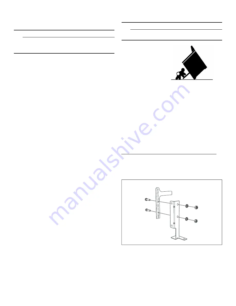
WARNING

TIP OVER HAZARD

Installing the anti-tip bracket

1.

Ensure that the electrical connection and the gas 

connection are in the correct position.

2.

Assemble the bracket.

A child or adult can tip the 

range over and be killed. 
Install the anti-tip device 

to the structure and/or the 

range. Verify the anti-tip 

device has been properly 

installed and engaged.
Engage the range to the 

anti-tip device. Ensure the 

anti-tip device is re-

engaged when the range 

is moved.
Re-engage the anti-tip device if the range is moved. 

Do not operate the range without the anti-tip device 

in place and engaged. 
See installation instructions for details.
Failure to follow the instructions in this manual can 

result in death or serious burns to children and 

adults.

Check for proper installation and use of the anti-tip 

bracket.

 Carefully tip the range forward pulling from 

the back to ensure that the anti-tip bracket engages 

the range leg and prevents tip-over. The range 

should not move more than 1” (2.5cm).

Содержание HDS8045C

Страница 1: ...Installation Manual Free standing range HDS8055U HDS8055C HDS8045U HDS8045C HDS8655U HDS8655C HDS8645U HDS8645C ...

Страница 2: ......

Страница 3: ...m 12 Fitting the Adjustable Feet 12 Connect Gas Supply 13 Install Appliance 14 Connect Electrical Supply 16 Burner Cap Placement 20 Check the Installation 21 Test for Gas Leaks 21 Conversion to Propane Gas LPG 22 Technical Service 25 How to Obtain Warranty Service 25 Wiring Diagram for HDS8 5 26 9 Safety DefinitionsSafetyDefinitions 9 WARNING This indicates that death or serious injuries may occur...

Страница 4: ...72 2 28 60 6 R QRW WU WR OLJKW DQ DSSOLDQFH R QRW WRXFK DQ HOHFWULFDO VZLWFK R QRW XVH DQ SKRQH LQ RXU EXLOGLQJ PPHGLDWHO FDOO RXU JDV VXSSOLHU IURP D QHLJKERU V SKRQH ROORZ WKH JDV VXSSOLHU V LQVWUXFWLRQV I RX FDQQRW UHDFK RXU JDV VXSSOLHU FDOO WKH ILUH GHSDUWPHQW QVWDOODWLRQ DQG VHUYLFH PXVW EH SHUIRUPHG E D TXDOLILHG LQVWDOOHU VHUYLFH DJHQF RU WKH JDV VXSSOLHU I WKH LQIRUPDWLRQ LQ WKHVH LQVWUXF...

Страница 5: ...nstallation Code CSA B149 1 The appliance must be electrically grounded in accordance with local codes or in the absence of local codes with the National Electrical Code NFPA 70 latest edition or in Canada the Canadian Electric Code CSA C22 1 02 Electric Safety WARNING Before you plug in an electrical cord or turn on power supply make sure all controls are in the OFF position Be sure your applianc...

Страница 6: ...lied with this unit must also be used The appliance is shipped from the factory for use with natural gas It must be converted for use with propane A qualified technician or installer must do the conversion This appliance has been certified for safe operation up to a height of 10 000 ft Exception To use it with propane gas the appliance must be converted in accordance with the propane conversion in...

Страница 7: ...igh Altitude Installation This appliance has been tested for operation up to an altitude of 10 000 ft 3 048 m elevation above sea level If desired for altitudes above 2 000 ft 610 m elevation above sea level adjustments may be made Burners should be checked at the lowest setting if the flame is not stable the simmer should be increased until the flame is stable This can be done by adjusting the by...

Страница 8: ...for USA Note Additional materials may be necessary for installation in solid surface countertops Contact the countertop manufacturer Parts Included 30 36 Removing Packaging See the diagram on the packaging If straps are present cut the straps Cut plastic down back of unit making sure not to cut the unit Remove plastic film Lift the cardboard carton from the top of the range and dispose of Remove t...

Страница 9: ...ʓʘ ʐ ʓʘ ʎ ʚ B minimum 18 457 mm C minimum 30 762 mm clearance between the top of the cooking surface and the bottom of the unprotected wood or metal cabinet D 30 minimum 30 762 mm 36 minimum 36 914 mm E minimum 25 635 mm F maximum 13 330 mm G 30 minimum 30 762 mm 36 minimum 36 914 mm Zero clearance between adjacent combustible construction below the countertop surface and sides of the appliance H ...

Страница 10: ...Intertek Clearances of less than 3 76 mm should be approved by the local codes and or by the local authority having jurisdiction Low Backguard Installation applicable both with non combustible back wall and combustible back wall Option 1 A 12 305 mm and B 28 711 mm Option 2 A 28 711 mm and B 12 305 mm purchased separately Clearances from non combustible materials are not part of the ANSI Z21 1 sco...

Страница 11: ...result in injury Do not place the removed door down on sharp or pointed objects as this could break the glass Lay on a flat smooth surface positioned so that the door cannot fall over To avoid injury or damage make sure that you read the above WARNING before attempting to remove the oven door 1 Open the oven door to its fully open position 2 Lock the two hinges on the left and right using the lock...

Страница 12: ...pproximately 3 4 19 mm to unhook the hinges from the slots and then pull it out towards you until the hinges are clear of the oven housing 5 Place the door in a convenient and stable location for cleaning 6 Refit the door in the reverse order in which it was removed Fitting the Rear Vent Trim 1 The rear vent trim is nested in the styrofoam packaging Remove the packaging and the protective film fro...

Страница 13: ...ar of the appliance Install the pressure regulator supplied with unit to gas inlet Postion the gasket supplied with unit in between the inlet and the regulator Position the regulator to have it cap D Page 23 easily accessible Turn the nut on gas inlet to hand tighten plus 1 3 turn Install the gas pipe to the regulator using Teflon tape or pipe joint compound resistant to propane gas and natural ga...

Страница 14: ...pressures in excess of 1 2 psi 3 5kPa The appliance must be isolated from the gas supply piping system by closing its individual manual shut off valve during any pressure testing of the gas supply piping system at test pressures equal to or less than 1 2 psi 3 5kPa Install Appliance 9 WARNING TIP OVER HAZARD Installing the anti tip bracket 1 Ensure that the electrical connection and the gas connec...

Страница 15: ... and screws A qualified technician must verify suitability of the materials in accordance with the type and condition of the wall 7 Use the following distances for the distance from the side of the appliance to the bracket holes 8 After having positioned and leveled the appliance move the bracket close to the rear of the appliance and anchor it to the floor with the two washers and screws A qualif...

Страница 16: ...uld be plugged directly into a properly grounded receptacle Do not cut or remove the grounding prong from this plug Preparation for Power Connection 9 WARNING WARNING Risk of Electric Shock or Fire Grounding through the neutral conductor is prohibited for new branch circuit installations 1996 NEC mobile homes and recreational vehicles or in an area where local codes prohibit grounding through the ...

Страница 17: ...Remove the grounding strap from the center post on the terminal block Therefore remove the hexagonal nut of the neutral pin Remove the fork type connector of the groundling link Mount the hexagonal nut on the neutral pin again Remove the green hexagonal screw and the ring connector from the grounding The strap will not be needed Remove it from the unit 6 Attach the insulated grounding wire to the ...

Страница 18: ... relief and tighten clamp Note Make sure the strain relief is secured properly 5 Insert the flat washer 6 Attach the red wire to the left junction block terminal using one of the hexagonal nuts 7 Attach the white wire to the center junction block terminal using one of the hexagonal nuts 8 Attach the black wire to the right junction block terminal using one of the hexagonal nuts 9 Tighten all conne...

Страница 19: ...ire connection is preferred but where local codes and ordinances permit grounding through neutral and or conversion to four wire is impractical the unit can be connected to the power supply via a three wire connection 1 Disconnect the electrical power at the breaker box Remove the terminal block cover to expose the terminal block 2 Insert the power supply cable into the terminal block through the ...

Страница 20: ... the cooktop One of the three bars on the burner base should line up with the notch and prevent the base from rotating The small hole or cutout near the edge should also line up with the igniter Pay special attention to avoid damaging the igniter during installation of the base See Illustration below Once each base is located and resting evenly place each burner cap on its correct burner base See ...

Страница 21: ...gas leaks with a flame Leak testing is to be conducted by the installer according to the instructions given in this section 1 Turn on gas 2 Apply a non corrosive leak detection fluid Include all joints and fittings between the shutoff valve and the appliance Include gas fittings and joints in the appliance if connections may have been disturbed during installation 3 Inspect for leaks Bubbles appea...

Страница 22: ...ge manifold must remain in the supply line Use a flexible metal appliance connector or rigid pipe to connect the range to the gas supply The connector should have an inner diameter of 1 2 and be 5 ft 1 5 m or less in length Exception Maximum connector length in Massachusetts installations is 3 ft 0 9 m In Canada the connector must be single wall metal and not longer than 6 ft 1 8 m Save the orific...

Страница 23: ...cover A and burner cup B from the burner C 3 Remove the nozzle D and replace it with an appropriate nozzle for the new type of gas Standard output burner high output burner Type of gas Pressure in W C P Burner Type Nozzle Number Bypass Min Power Max Power Natural gas 5 Dual flame burner external 180 S4 Gap 1000 BTU 0 3 kW 18000 BTU 5 3 kW Dual flame burner internal 75 Gap Large burner 145 Gap 2400...

Страница 24: ...of the gas burners have been set 9 Connect the appliance to the power supply Checking functions after the conversion The flames must not go out when switching over swiftly from the high to the low setting Note Stick the adhesive label included with the nozzle set over the rating plate of the appliance to document the changeover to a different gas type Test for Gas Leaks After the conversion it is ...

Страница 25: ...Warranty Service To obtain warranty service for your Product you should contact Bosch Customer Service at 1 800 944 2904 to schedule a repair Model E number and FD number When you contact our service please have the Model E number and the FD number for your appliance available You can find this information on the rating label on the back side of the appliance on the underside of the projecting con...

Страница 26: ...UYLFLQJ WLTXHWH OHV ILOV DYDQW GH GpFRQQHFWHU SRXU OHV FRQWUROHV GH VHUYLFH 8QH HUUHXU GDQV OH ILODJH SHXW SURYRTXHU GHV RSpUDWLRQV GDQJHUHXVH HW LQFRUUHFWHV 9HULILH OD FRQIRUPLWp GH O RSpUDWLRQ DSUqV XQ HQWUHWLHQ 0DUFDU WRGRV OHV FDEOHV DQWHV GH GHVFRQHFWDU DO UHDOL DU HO PDQWHQLPLHQWR GH ORV PDQGRV RV HUURUHV GH FRQH LzQ SXHGHQ FDXVDU ERSHUDFLRQHV LQDGHFXDGDV SHOLJURVDV RPSUREDU HO IXQFLRQDPLHQW...

Страница 27: ...ture de ventilation arrière 36 Montage des pieds réglables 37 Branchement du gaz 37 Pose de l appareil 38 Brancher l alimentation électrique 40 Montage des chapeaux de brûleur 44 Vérification de l installation 45 Test pour fuites de gaz 45 Conversion gaz au propane LPG 46 Service technique 49 Comment bénéficier du service de garantie 49 Schéma de câblage pour HDS8 5 50 9 Définitions de sécuritéDéf...

Страница 28: ...DV WRXFKHU G LQWHUUXSWHXU GH FRXUDQW pOHFWULTXH 1H SDV XWLOLVHU GH WpOpSKRQHV GDQV O pGLILFH RPPXQLTXHU LPPpGLDWHPHQW DYHF OH IRXUQLVVHXU GH JD GHSXLV O DSSDUHLO WpOpSKRQLTXH G XQ YRLVLQ 5HVSHFWHU OHV GLUHFWLYHV GX IRXUQLVVHXU GH JD 6 LO V DYqUH LPSRVVLEOH GH MRLQGUH OH IRXUQLVVHXU GH JD FRPPXQLTXHU DYHF OHV SRPSLHUV 8WLOLVHU OHV VHUYLFHV G XQ LQVWDOODWHXU RX G XQH DJHQFH GH VHUYLFHV TXDOLILpV RX ...

Страница 29: ...nada au code national CSA B149 1 d installation du gaz naturel et du propane L appareil doit être mise à la terre en conformité aux codes locaux ou en l absence de tels codes à la dernière version du National Electric Code NFPA 70 ou au Canada au code canadien de l électricité CSA C22 1 02 Sécurité électrique AVERTISSEMENT Avant tout raccordement de cordon électrique ou toute mise sous tension ass...

Страница 30: ... une conduite de gaz en métal ne peut pas être utilisée veuillez vous adresser à un électricien agréé local ou aux codes électriques locaux pour obtenir une mise à la terre appropriée AVIS DE SÉCURITÉ IMPORTANT l incinération de combustible gazeux de cuisson peut générer des sous produits qui figurent sur la liste des substances reconnues par l État de Californie comme étant cancérigènes ou nuisib...

Страница 31: ...ations sur la ventilation Il est vivement recommandé d installer une hotte aspirante au dessus de cet appareil La hotte aspirante doit être installée conformément aux instructions qui l accompagnent ATTENTION L appareil ne devrait pas être installé avec un système de ventilation qui souffle l air vers les brûleurs Ce type de système de ventilation peut causer des problèmes d allumage et de combust...

Страница 32: ...matériaux supplémentaires peuvent être nécessaires pour l installation de comptoirs à surface solide Contactez le fabricant du comptoir Pièces comprises 30 po 36 po Pour enlever l emballage Voir le schéma sur l emballage S il y a des sangles coupez les Coupez le plastique à l arrière de l appareil en vous assurant de ne pas couper l appareil Retirez le film protecteur Soulevez l étui en carton du ...

Страница 33: ... ʓʘ ʐ ʓʘ ʎ ʚ B minimum 18 po 457 mm C dégagement minimal de 30 po 762 mm entre le dessus de la surface de cuisson et le dessous de l armoire en bois ou en métal non protégée D 30 po minimum 30 po 762 mm 36 po minimum 36 po 914 mm E minimum 25 po 635 mm F maximum 13 po 330 mm G 30 po minimum 30 po 762 mm 36 po minimum 36 po 914 mm Dégagement nul entre la construction de combustible adjacente en des...

Страница 34: ... de moins de 3 po 76 mm doivent être approuvés par le et ou par l autorité locale compétente Protection arrière basse Installation applicable à la fois avec paroi arrière non combustible et paroi arrière combustible Option 1 A 12 po 305 mm et B 28 po 711 mm Option 2 A 28 po 711 mm et B 12 po 305 mm Acheté séparément Dégagements des matériaux incombustibles ne font pas partie du domaine d applicati...

Страница 35: ...sont bien en place avant de retirer la porte De plus ne forcez pas la porte à s ouvrir ou à se fermer la charnière pourrait être endommagée et des blessures pourraient en résulter Ne posez pas la porte sur des objets pointus ou tranchants car cela pourrait briser la vitre Posez la porte sur une surface plane et lisse de sorte à ne pas la faire tomber Pour éviter de vous blesser ou d endommager l a...

Страница 36: ...rs être retirée mais le loquet se referme et vous pince ou vous coupe la main 4 La porte est lourde Saisissez les côtés de la porte fermement et des deux mains Ne saisissez pas la porte par la poignée En maintenant l angle de la porte au même niveau soulevez cette dernière d environ 3 4 po 19 mm vers le haut pour décrocher les charnières des fentes puis tirez la vers vous jusqu à ce que les charni...

Страница 37: ... ci dessus Lorsqu il est utilisé avec du gaz naturel la pression fournie au régulateur doit se situer entre 6 po et 10 5 po de la colonne d eau Pour convertir l appareil au gaz propane voir Conversion au gaz propane GPL Un technicien ou un installateur qualifié doit procéder à la conversion Utilisez un tuyau de gaz flexible d une longueur d au moins 5 pi 1 5 m L admission de gaz de l appareil est ...

Страница 38: ...ion des fuites est terminé aucune bulle n apparaît le test est terminé 5 Essuyez tout résidu de la solution savonneuse ou du liquide de détection de fuite Remarques importantes concernant le raccord au gaz L appareil et son propre robinet d arrêt doivent être déconnectés de la canalisation du système d alimentation en gaz au cours de tests de pression de ce système aux pressions qui dépassent 1 2 ...

Страница 39: ... 9 et 10 5 Respectez la distance spécifiée entre le côté de l appareil et les trous des supports 6 Déplacez le support sur le mur et fixer avec les deux rondelles et vis Un technicien qualifié doit vérifier l adéquation des matériaux en fonction du type et de l état du mur 7 Respectez les distances suivantes pour déterminer la distance entre le côté de l appareil et les trous des supports 8 Après ...

Страница 40: ...on de la cuisinière au bornier Accédez au bornier en retirant le couvercle situé dans le coin inférieur droit du panneau arrière de la cuisinière 9 AVERTISSEMENT INSTRUCTIONS DE MISE À LA TERRE L électroménager HDS8 5C est doté d une fiche à quatre broches mise à la terre pour vous protéger contre le danger d électrocution La fiche doit être utilisée dans une prise correctement mise à la terre Ne ...

Страница 41: ...trique dans le bornier en le faisant passer par le trou inférieur 4 Montez le réducteur de tension non fourni avec la cuisinière à travers le trou de la plaque métallique dans le panneau arrière situé sous le bornier et fixez fermement Acheminez les fils du câble d alimentation à travers la décharge de traction et serrez la pince Remarque Assurez vous que la décharge de traction est correctement f...

Страница 42: ...i vous avez besoin d un trou plus grand pour la décharge de traction non fourni avec la cuisinière retirez la plaque métallique Faites le pivoter de 180 pour avoir un plus grand trou pour le câble d alimentation et montez le à nouveau 3 Insérez le câble d alimentation électrique dans le bornier en le faisant passer par le trou inférieur 4 Montez le réducteur de tension non fourni avec la cuisinièr...

Страница 43: ...ment à l aide d un des écrous hexagonaux 8 Raccordez le fil noir à la borne droite du bloc de raccordement à l aide d un des écrous hexagonaux 9 Sécurisez convenablement le cordon de sûreté 9 AVERTISSEMENT AVERTISSEMENT Le cordon de sûreté fournie avec votre cordon de cuisinière doit être installé convenablement 10 Vissez bien tous les raccordements et replacez le couvercle du bornier Remarque Ne ...

Страница 44: ...fonctionner correctement Si les pièces du brûleur ne sont pas correctement positionnées un ou plusieurs des problèmes suivants peuvent survenir La flamme du brûleur est trop élevée Des flammes jaillissent des brûleurs Les brûleurs ne s allument pas La flamme du brûleur n est pas uniforme Une odeur de gaz se dégage du brûleur Positionnement du chapeau et de la base du brûleur Après avoir terminé le...

Страница 45: ...ppareil fonctionner pendant 4 à 5 minutes et réévaluez la situation avant d effectuer les réglages Test pour fuites de gaz 9 AVERTISSEMENT RISQUE D INCENDIE Ne vérifiez jamais les fuites de gaz avec une flamme L installateur doit procéder au test de fuites selon les directives fournies dans cette section 1 Ouvrez le gaz 2 Appliquez un liquide de détection de fuite non corrosif Incluez tous les joi...

Страница 46: ...mme doit rester dans la conduite d alimentation Utilisez un connecteur métallique flexible ou un tuyau rigide pour brancher l appareil à l alimentation en gaz Le connecteur doit avoir un diamètre intérieur de 1 2 po et une longueur de 5 pieds 1 5 m ou moins Exception la longueur maximale des connecteurs dans les installations du Massachusetts est de 3 pieds 0 9 m Au Canada le connecteur doit être ...

Страница 47: ...ez le capot du brûleur A et la coupelle du brûleur B du brûleur C 3 Enlevez la buse D et remplacez la par une buse adaptée au nouveau type de gaz Brûleur de puissance standard brûleur de haute puissance Type de gaz Pression en W C P Type de brûleur Nombre de buses Dériva tion Puis sance Min Puissance max Gaz naturel 5 po Brûleur à flamme double externe 180 S4 Écart 1000 BTU 0 3 kW 18000 BTU 5 3 kW...

Страница 48: ...es 2 à 8 jusqu à ce que tous les brûleurs à gaz soient réglés 9 Branchez l appareil à l alimentation électrique Vérification des fonctions après la conversion Les flammes ne doivent pas s éteindre lors du passage rapide de la position haute à la position basse Remarque Collez l étiquette adhésive fournie avec la buse sur la plaque signalétique de l appareil pour signaler le passage à un autre type...

Страница 49: ...qui disposent des pièces de rechange d origine adaptées à votre appareil Comment bénéficier du service de garantie Pour obtenir un service sous garantie pour votre produit contactez le département de service après vente de Bosch au 1 800 944 2904 pour planifier une réparation Numéro de modèle E et numéro FD Quand vous communiquez avec le service veuillez avoir à portée de main le numéro de modèle ...

Страница 50: ...VHUYLFLQJ WLTXHWH OHV ILOV DYDQW GH GpFRQQHFWHU SRXU OHV FRQWUROHV GH VHUYLFH 8QH HUUHXU GDQV OH ILODJH SHXW SURYRTXHU GHV RSpUDWLRQV GDQJHUHXVH HW LQFRUUHFWHV 9HULILH OD FRQIRUPLWp GH O RSpUDWLRQ DSUqV XQ HQWUHWLHQ 0DUFDU WRGRV OHV FDEOHV DQWHV GH GHVFRQHFWDU DO UHDOL DU HO PDQWHQLPLHQWR GH ORV PDQGRV RV HUURUHV GH FRQH LzQ SXHGHQ FDXVDU ERSHUDFLRQHV LQDGHFXDGDV SHOLJURVDV RPSUREDU HO IXQFLRQDPLH...

Страница 51: ......

Страница 52: ...1901 Main Street Suite 600 Irvine CA 92614 800 944 2904 www bosch home com 2020 BSH Home Appliances 000724 9001485906 9001485906 ...

Отзывы: