background image

-7-

Power Tool-Specific Safety Warnings

torque reactions or kickback forces, if 

proper precautions are taken.
Never place your hand near the rotating 

accessory.  Accessory may kickback over 

your hand.
Do not position your body in the area 

where power tool will move if kickback 

occurs.  Kickback will propel the tool in di-

rection opposite to the wheel’s movement 

at the point of snagging.
Use special care when working corners, 

sharp edges etc. Avoid bouncing and snag-

ging the accessory. Corners, sharp edges 

or bouncing have a tendency to snag the 

rotating accessory and cause loss of con-

trol or kickback.
Do not attach a saw chain woodcarving 

blade or toothed saw blade. Such blades 

create frequent kickback and loss of con-

trol.


▶ Safety Warnings Specific  

for Grinding and Abrasive  

Cutting-Off Operations

Use only wheel types that are recom-

mended for your power tool and the 

specific guard designed for the selected 

wheel.  Wheels for which the power tool 

was not designed cannot be adequately 

guarded and are unsafe.
The grinding surface of centre depressed 

wheels must be mounted below the plane 

of the guard lip. An improperly mounted 

wheel that projects through the plane of 

the guard lip cannot be adequately pro-

tected.
The guard must be securely attached to 

the power tool and positioned for maxi-

mum safety, so the least amount of wheel 

is exposed towards the operator. The 

guard helps to protect operator from bro-

ken wheel fragments and accidental con-

tact with wheel.
Wheels must be used only for recom-

mended applications. For example: do 

not grind with the side of cut-off wheel. 

Abrasive cut-off wheels are intended for 

peripheral grinding, side forces applied to 

these wheels may cause them to shatter.

Always use undamaged wheel flanges 

that are of correct size and shape for 

your selected wheel. Proper wheel flang-

es support the wheel thus reducing the 

possibility of wheel breakage. Flanges for 

cut-off wheels may be different from grind-

ing wheel flanges.
Do not use worn down wheels from larg-

er power tools. Wheel intended for larger 

power tool is not suitable for the higher 

speed of a smaller tool and may burst.


▶ Additional Safety Warnings  

Specific for Abrasive  

Cutting-Off Operations

Do not “jam” the cut-off wheel or apply 

excessive pressure. Do not attempt to 

make an excessive depth of cut. Over-

stressing the wheel increases the loading 

and susceptibility to twisting or binding of 

the wheel in the cut and the possibility of 

kickback or wheel breakage.
Do not position your body in line with 

and behind the rotating wheel. When the 

wheel, at the point of operation, is moving 

away from your body, the possible kick-

back may propel the spinning wheel and 

the power tool directly at you.
When wheel is binding or when inter-

rupting a cut for any reason, switch off 

the power tool and hold the power tool 

motionless until the wheel comes to a 

complete stop. Never attempt to remove 

the cut-off wheel from the cut while the 

wheel is in motion otherwise kickback 

may occur. Investigate and take correc-

tive action to eliminate the cause of wheel 

binding.
Do not restart the cutting operation in 

the workpiece. Let the wheel reach full 

speed and carefully reenter the cut. The 

wheel may bind, walk up or kickback if the 

power tool is restarted in the workpiece.
Support panels or any oversized work-

piece to minimize the risk of wheel pinch-

ing and kickback. Large workpieces tend 

to sag under their own weight. Supports 

must be placed under the workpiece near 

the line of cut and near the edge of the 

workpiece on both sides of the wheel.

160992A4FH 05-19 GWX18V-50PC.indd   7

6/3/19   7:28 AM

Содержание GWX18V-50PC

Страница 1: ...nes d utilisation de sécurité Instrucciones de funcionamiento y seguridad Call Toll Free for Consumer Information Service Locations Pourobtenirdesinformationsetlesadressesdenoscentresdeserviceaprès vente appelezcenumérogratuit Llame gratis para obtener información para el consumidor y ubicaciones de servicio 1 877 BOSCH99 1 877 267 2499 www boschtools com GWX18V 50PC 160992A4FH 05 19 GWX18V 50PC i...

Страница 2: ... 9 Functional Description and Specifications 11 Basic X Lock Operation 12 Brake Operation 13 Assembly 14 Inserting the Bluetooth Connectivity Tool Module 14 Installing Side Handle 14 Hand Shield 14 Installing Wheel Guards Type 27 and Type 41 1A Wheel Guards 15 Mounting and Removing X Lock Accessories 16 Abrasive Type 27 Grinding Wheel Sanding Flap Disk Assembly 18 Abrasive Type 41 1A Cutting Wheel...

Страница 3: ...nders away while operating a power tool Distractions can cause you to lose control Electrical Safety Power tool plugs must match the outlet Never modify the plug in any way Do not use any adapter plugs with earthed grounded power tools Unmodified plugs and matching outlets will reduce risk of electric shock Avoid body contact with earthed or grounded surfaces such as pipes radia tors ranges and re...

Страница 4: ...entive safe ty measures reduce the risk of starting the power tool accidentally Store idle power tools out of the reach of children and do not allow persons unfamiliar with the power tool or these instructions to operate the power tool Power tools are dangerous in the hands of untrained users Maintain power tools Check for misalign ment or binding of moving parts break age of parts and any other c...

Страница 5: ... designed and recommended by the tool manufacturer Just because the accessory can be attached to your power tool it does not assure safe operation The rated speed of the accessory must be at least equal to the maximum speed marked on the power tool Accessories running faster than their rated speed can break and fly apart The outside diameter and the thickness of your accessory must be within the c...

Страница 6: ...y height gage may not be clamped properly and separate from the tool causing personal injury and or prop erty damage Always inspect accessory mount and ac cessory clamping flange before use Do not use the tool or accessory if the ac cessory mount or accessory is damaged or deformed Accessories that are not clamped properly may cause personal in jury and or property damage Check for presence or bui...

Страница 7: ...m to shatter Always use undamaged wheel flanges that are of correct size and shape for your selected wheel Proper wheel flang es support the wheel thus reducing the possibility of wheel breakage Flanges for cut off wheels may be different from grind ing wheel flanges Do not use worn down wheels from larg er power tools Wheel intended for larger power tool is not suitable for the higher speed of a ...

Страница 8: ...our risk from these exposures varies de pending on how often you do this type of work To reduce your exposure to these chemicals work in a well ventilated area and work with approved safety equipment such as those dust masks that are special ly designed to filter out microscopic par ticles Use extra caution when making a pocket cut into existing walls or other blind ar eas The protruding wheel may...

Страница 9: ...l speed at no load n Rated speed Maximum attainable speed min Revolutions or reciprocation per minute revolutions strokes surface speed orbits etc per minute 0 Off position zero speed zero torque 1 2 3 I II III Selector settings speed torque or position settings Higher number means greater speed Infinitely variable selector with off speed is increasing from 0 setting Arrow action in the direction ...

Страница 10: ...aboratories This symbol designates that this component is recognized by Underwriters Laboratories This symbol designates that this tool is listed by Underwriters Laboratories to United States and Canadian Standards This symbol designates that this tool is listed by the Canadian Standards Association This symbol designates that this tool is listed by the Canadian Standards Association to United Sta...

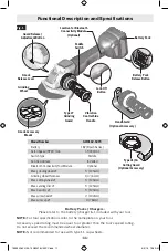
Страница 11: ...ype Paddle Run Down Brake Included Bluetooth Connectivity Tool Module Optional Max grinding wheel 5 125mm Grinding wheel thickness 1 4 6 mm Max cutting wheel 5 125mm Max sanding disc 5 125mm Max flap disc 5 125mm Max wire wheel 4 102mm Max wire cup 3 76mm Battery Packs Chargers Please refer to the battery charger list included with your tool NOTE For tool specifications refer to the nameplate on y...

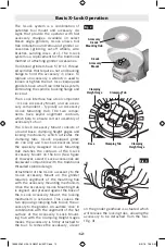
Страница 12: ...ng mechanism which activates the clamping tabs X Lock equipped grind ers can only use X Lock accessories since the specially designed X Lock Mounting Hub matches the contours of the X Lock Accessory Mount on the tool See figure 2 However select X Lock accessories are backward compatible with the traditional threaded spindle design Attachment of the X Lock accessory to the X Lock Accessory Mount on...

Страница 13: ... damage and or personal injury Your grinder is equipped with an automat ic electric brake which is designed to stop the accessory from spinning in approxi mately two 2 seconds after you release the trigger switch This feature helps im prove jobsite productivity Braking starts once the power is turned off The brake requires a charged battery to function Stopping time will vary de pending on among o...

Страница 14: ...hread handle into either side of gear housing depending on personal pref erence comfort and operation being per formed Fig 4 The handle should always be installed onto the guard protected side of the tool see figure 6 Use the side handle for safe control and ease of operation Hand Shield The hand shield is to be used with back ing pads sanding discs and wire brushes to keep fingers and hand away f...

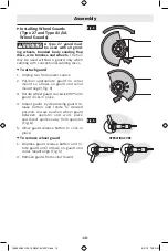
Страница 15: ... so arrows on guard and collar mount align Fig 5 3 Rotate wheel guard clockwise 90º until guard clicks in place 4 Adjust guard by depressing guard re lease button and rotate to desired position Always position wheel guard between operator and work piece and direct sparks away from operator Fig 6 5 Allow guard release button to click in place To remove wheel guard 1 Depress guard release button and...

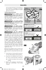
Страница 16: ...ock Release Lever while ac cessory is moving Make sure that the ac cessory has come to a complete stop be fore removing the accessory Ejecting accessory while still spinning could cause personal injury and or property damage Verify that the accessory and the X Lock Accessory Mount are not deformed and are free from dirt If necessary clean the area around the two X Lock Clamping Tabs Verify that bo...

Страница 17: ...ter inspecting and installing an acces sory position yourself and bystanders away from the plane of the rotating acces sory and run the power tool at maximum no load speed for one minute Damaged accessories will normally break apart dur ing this test time Before removing the accessory Make sure that the power tool has come to a com plete stop and is disconnected from pow er 1 Orient the tool to pr...

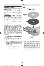
Страница 18: ... Fig 11 see instructions on page 15 Fig 11 Type 27 Wheel Guard Type 27 Grinding Wheel Abrasive Type 41 1A Cutting Wheel Assembly Always use type 41 1A cutting guard for cut ting operations Other guards or attach ments may not protect operator in the event of a wheel burst To install cutting wheel Fig 12 see in structions on page 15 Fig 12 Type 41 1A Wheel Guard Type 27 Cutting Wheel Type 41 1A Cut...

Страница 19: ...g Fig 4 Ensure that hand shield is positioned between hand and backing pad sanding disc or wire brush To install backing pad and sanding disc Fig 13 1 Inspect Hand Shield to ensure that it is properly attached to the grinder 2 Place the Backing Pad onto the X Lock Accessory Mount with the rectangular openings positioned around the X Lock Clamping Tabs 3 Center the Sanding Disc on top of the Backin...

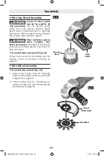
Страница 20: ...ush accessories without gloves may result in personal injury To install wire cup brush Fig 14 Follow instructions for Mounting and Re moving X Lock Accessories starting on page 15 Wire Wheel Assembly To install wire wheel Fig 15 1 Inspect and adjust Type 27 Grinding Guard to the proper position as shown in figure 6 on page 14 2 Follow instructions for Mounting ac cessory to the tool and Removing t...

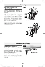
Страница 21: ...utton and slide the bat tery pack forward Fig 16 Press the battery pack release button again and slide the battery pack complete ly out of tool housing Operating Instructions Paddle Switch Fig 17 The paddle switch has a Lock OFF feature to help prevent accidental startups TO TURN TOOL ON push Lock Off switch backward to unlock the paddle switch then squeeze paddle switch TO TURN TOOL OFF release p...

Страница 22: ...wheels have sharp edges which tend to bite or cut into the work piece when pushed forward Fig 18 Metal Cutting A Type 1 wheel guard may not be included with this tool but is required when using a cutting wheel Cutting with a type 27 wheel guard may not provide the operator sufficient protection in the event of a wheel burst With this grinder it is possible to perform cutting of limited small stock...

Страница 23: ...urface allowing the tool to operate at high speed Sanding rate is greatest when the tool operates at high speed 3 Maintain a 10 to 15 angle between the tool and work surface Fig 20 4 Continuously move the tool at a moder ate speed to avoid creating gouges in the work surface 5 Remove the tool from work surface be fore turning tool off Allow the tool to stop rotating before laying it down Tip Guide...

Страница 24: ...ing tool off Allow the tool to stop rotating before laying it down Tip The tips of the brush do the work Operate wire brushes with the lightest pressure so only the tips of the wire come in contact with the work piece If heavier pressures are used the wires will be over stressed resulting in a wiping action and a shortened brush life due to wire fatigue Applying the side or edge of the brush to th...

Страница 25: ...also do it when changing the tool photo E Connection status bar Here you can see the connection signal strength indicated by vertical bars You can use toggle switch to disconnect the tool from you mobile device F Soft Start Allows speed ramp up of grinder G User Interface Customize tool inter face and usage settings H Factory Reset toggle switch you can reset tool settings back to factory de fault...

Страница 26: ...ce ment motor specially designed for your tool should be used Cleaning Certain cleaning agents and solvents damage plastic parts Some of these are gasoline carbon tetrachloride chlorinated cleaning solvents ammonia and household deter gents that contain ammonia Ventilation openings and switch levers must be kept clean and free of foreign matter Do not attempt to clean by insert ing pointed objects...

Страница 27: ...es opérations de brossage métallique 33 Avertissements supplémentaires concernant la sécurité 33 Symboles 34 Description fonctionnelle et spécifications 36 Fonctionnement basique du système X Lock 37 Opération de freinage 38 Assemblage 39 Insertion du module d outil de connectivité Bluetooth 39 Installation de la poignée latérale 39 Écran de protection de la main 39 Installation des dispositifs de...

Страница 28: ...uisent des étincelles qui ris quent d enflammer les poussières ou les vapeurs Éloignez les enfants et les visiteurs quand vous vous servez d un outil électroportatif Vous risquez une perte de contrôle si on vous distrait Sécurité électrique Les fiches des outils électroportatifs doivent corre spondreàlaprise Il ne faut absolument jamais modi fier la fiche N utilisez pas d adaptateur de prise avec ...

Страница 29: ...che de la prise secteur et ou retirez le bloc piles de l outil électrique avant d y apporter de quelconques modifications de changer d accessoire ou de ranger l outil électrique De telles mesures de sécurité préventive réduisent le risque de démarrage in tempestif de l outil électroportatif Rangez les outils électroportatifs dont vous ne vous servez pas hors de portée des enfants et ne permettez p...

Страница 30: ...é conçu risque de présenter un danger et de causer des blessures corporelles N utilisez pas d accessoires qui n ont pas été spéci fiquement conçus et recommandés par le fabricant de l outil Le simple fait qu un accessoire puisse être at taché à votre outil électroportatif ne garantit pas un fonc tionnement sans danger La vitesse nominale de l accessoire doit être au moins égale à la vitesse maximu...

Страница 31: ...t ne pas être fixés correctement ce qui peut entraîner des blessures et ou des dommages matériels Assurez vous que la surface supérieure de la bride de l accessoire n est pas au dessus du sommet de la jauge de hauteur de l accessoire pour s assurer qu elle est bien sécurisée Les accessoires qui se trouvent au dessus de la jauge de hauteur de l accessoire peuvent ne pas être sécurisés correctement ...

Страница 32: ...e et l application de forces latérales à ces meules peuvent les faire éclater Utilisez toujours des brides non endommagées d une taille et d une forme qui conviennent à la meule sélec tionnée Les brides de meule appropriées soutiennent la meule réduisant ainsi la possibilité que la meule se casse Les brides pour meules de tronçonnage peuvent être dif férentes des brides pour d autres types de meul...

Страница 33: ...aités chi miquement Le niveau de risque dû à cette exposition varie avec la fréquence de ces types de travaux Pour réduire l expositionàcesproduitschimiques ilfauttravaillerdans un lieu bien ventilé et porter un équipement de sécurité approprié tel que certains masques à poussière conçus spécialement pour filtrer les particules microscopiques Faitesparticulièrementattentionquandvousexécutez une co...

Страница 34: ... mouvement alternatif par minute tours coups vitesse en surface orbites etc par minute 0 Position d arrêt vitesse zéro couple zéro 1 2 3 I II III Réglages du sélecteur Réglages de vitesse de couple ou de position Un nombre plus élevé signifie une vitesse plus grande Sélecteur variable à l infini avec arrêt La vitesse augmente depuis le réglage 0 Flèche action dans la direction de la flèche Courant...

Страница 35: ...et outil est approuvé par Underwriters Laboratories Ce symbole indique que ce composant est reconnu par Underwriters Laboratories Ce symbole signifie que cet outil est approuvé par Underwriters Laboratories selon les normes des États Unis et du Canada Ce symbole signifie que cet outil est approuvé par l Association canadienne de normalisation Ce symbole signifie que cet outil est approuvé par l As...

Страница 36: ...ctivité Bluetooth En option max de la meule 5 125mm Épaisseur de la meule 1 4 6 mm max du disque de coupe 5 125mm max du disque de ponçage 5 125mm max du disque à volets abrasifs 5 125mm max de la brosse métallique circulaire 4 102mm max de la brosse forme coupelle 3 76mm Bloc piles chargeurs Veuillez vous référer à la liste des piles chargeurs accompagnant votre outil REMARQUE Pour spécifications...

Страница 37: ... active les languettes de fixation Les meuleuses équipées du système X Lock ne peuvent utiliser que des accessoires X Lock étant donné que l embout de montage X Lock spécialement conçu épouse les contours du support de montage d accessoire X Lock sur l outil voir Figure 2 Cependant certains ac cessoires X Lock sont rétrocompatibles avec les modèles traditionnels des broches filetées La fixation de...

Страница 38: ...du peut causer des dom mages matériels et ou des blessures Votre meuleuse est pourvue d un frein électrique automa tique qui est conçu pour arrêter la rotation de l accessoire auboutd environdeux 2 secondesaprèslerelâchement de l interrupteur à gâchette Cette fonctionnalité améliore la productivité sur le lieu de travail Le freinage commence dès que l alimentation électrique est désactivée Le frei...

Страница 39: ...l autre du boîtier de transmission selon votre préférence personnelle pour assurer le maximum de confort et en fonctiondel opérationeffectuée Lapoignéedoittoujours être installée sur le côté de l outil où se trouve le disposi tif de protection Fig 4 Utilisez la poignée latérale pour contrôler l outil facilement et en toute sécurité Écran de protection de la main L écran de protection de la main do...

Страница 40: ...tifdeprotectionde90degrés dans le sens des aiguilles d une montre jusqu à ce que vous entendiez le déclic indiquant qu il est bien en place 4 Ajustez le dispositif de protection en appuyant sur le bouton de libération du dispositif et faites le tourner jusqu à la position désirée Positionnez toujours le protège meule entre l opérateur et l ouvrage et dirigez les étincelles dans le sens opposé à ce...

Страница 41: ...onnez ja mais un levier de libération d un accessoire X Lock pendant que cet ac cessoire est en mouvement Assurez vous que l accessoire s est complètement arrêté avant de le retirer L éjection d un accessoire encore en train de tourner pour rait causer des blessures et ou des dommages matériels Vérifiez que l accessoire et le support de montage de l accessoire X Lock ne sont pas déformés ou couver...

Страница 42: ...u l accessoire vérifiez que ce derni er n est pas endommagé ou remplacez le par un acces soire en bon état Après l inspection et l installation d un accessoire tenez vous à distance du plan de l accessoire en mouvement et demandez à toute personne présente de faire de même et faites fonctionner l outil à sa vitesse à vide maximale pendant une minute Si un accessoire est endommagé il se cassera hab...

Страница 43: ... 38 Montage de la meule abrasive de type 27 et du disque de ponçage N utilisez pas d accessoires qui tournent de façon excentrique L outil vibrera excessive ment ce qui pourrait causer une perte de contrôle et l éclatement de l accessoire Pour installer la meuleuse ou le disque à volet abrasif Fig 11 voir les instructions à la page 38 Assemblage Fig 11 Protègemeule de type 27 Meule abrasive de typ...

Страница 44: ... du disque de support et du disque de ponçage Fig 13 1 Inspectez le masque de sécurité pour la main pour vous assurer qu il est attaché correctement à la meu leuse 2 Placez le tampon de soutien sur le support de mon tage de l accessoire X Lock de telle façon que les ouvertures rectangulaires soient positionnées autour des languettes de fixation X Lock 3 Centrez le disque de ponçage sur le dessus d...

Страница 45: ...res de brossage métalliques sans porter de gants pourrait causer des bles sures Installation de la brosse métallique en forme de coupelle Fig 14 Suivez les instructions pour le Montage et retrait des ac cessoires X Lock à partir de la page 38 Montage de la brosse métallique Installation de la brosse métallique Fig 15 1 Inspectez et ajustez le dispositif de protection pour le meulage de type 27 dan...

Страница 46: ...ement du bloc piles et faites glisser le bloc piles jusqu à ce qu il sorte complètement du bâti de l outil Consignes de fonctionnement Interrupteur à palette Fig 17 L interrupteur à palette est muni d une fonction de ver rouillage en position d arrêt qui empêche une mise en marche accidentelle POUR METTRE L OUTIL EN MARCHE ON poussez le bouton de verrouillage en position d arrêt vers l arrière pou...

Страница 47: ...yer l ouvrage quand on les pousse en avant Fig 18 Coupe de métaux Un protège meule de type 1 n est peut être pas inclus avec cet outil mais il est indis pensable de s en servir quand on utilise une molette L utilisation d un protège meule de type 27 risque de ne pas fournir une protection suffisante à l opérateur en cas d éclatement d une meule Avec cet outil il est possible de couper des quantité...

Страница 48: ...ssion sur la surface de travail de façon à permettre à l outil de fonctionner à grande vitesse Plus la vitesse de l outil sera élevée plus le ponçage sera rapide 3 Maintenez un angle de 10 à 15 degrés entre l outil et la surface de travail Fig 20 4 Déplacez continument l outil à une vitesse modérée pour éviter de faire des rayures sur la surface de tra vail 5 Éloignez l outil de la surface de trav...

Страница 49: ...lètement avant de le poser sur une surface quelconque Suggestion ce sont les bouts de la brosse qui font le travail Utilisez les brosses métalliques en appliquant le moins de pression possible afin que seules leurs extrémi tés entrent en contact avec l ouvrage Si vous exercez une pression excessive les soies s useront et se limiteront à essuyer l ouvrage au lieu de le frotter vigoureusement et leu...

Страница 50: ...des barres verticales Vous pouvez utiliser l interrupteur à bascule pour déconnecter l outil de votre dispositif mobile F Soft Start Démarrage en douceur permet d accélérer progressivement la vitesse de la meuleuse G User Interface Interface utilisateur personnali sez l interface de l outil et les paramètres d utilisation H Interrupteur à bascule Factory Reset Réinitialisa tion usine vous pouvez r...

Страница 51: ... Nettoyage Certains produits de nettoyage et solvants endommagent les pièces en plastique En voici quelques exemples l essence le tétrachlorure de car bone les solvants de nettoyage au chlore l ammoniac et les détergents domestiques contenant de l ammoniac Les ouvertures de ventilation et les leviers des interrupt eurs doivent être toujours propres et aucun corps étrang er ne doit y adhérer Ne ten...

Страница 52: ...s con cepillo de alambre 58 Symboles 59 Descripción funcional y especificaciones 61 Utilización básica del X Lock 62 Operación de freno 63 Ensamblaje 64 Inserción del módulo de conectividad Bluetooth para herramientas 64 Instalación del mango lateral 64 Escudo para la mano 64 Instalación de los protectores de la rueda protectores de la rueda de Tipo 27 y Tipo 41 1A 65 Montaje y remoción de los acc...

Страница 53: ...ánica Las distracciones pueden hacerle perder el control de la herramienta Seguridad eléctrica Los enchufes de las herramientas mecánicas deben coincidir con el tomacorriente No modifique nunca el enchufe de ningún modo No use enchufes adap tadores con herramientas mecánicas conectadas a tierra puestas a tierra Los enchufes no modificados y los tomacorrientes coincidentes reducirán el riesgo de sa...

Страница 54: ...ancar accidentalmente la herramienta mecánica Guarde las herramientas que no esté usando fuera del alcance de los niños y no deje que personas que no es tén familiarizadas con la herramienta mecánica o con estas instrucciones utilicen la herramienta Las herra mientas mecánicas son peligrosas en manos de usuarios que no hayan recibido capacitación Mantenga las herramientas eléctricas y sus acceso r...

Страница 55: ...ccesorio que no esté dañado Después de inspec cionar e instalar un accesorio posiciónese usted y posicione a las personas que estén presentes aleja dos del plano del accesorio que gira y haga funcionar la herramienta mecánicaa la máxima velocidad sin carga durante un minuto Normalmente los accesorios dañados seromperán en pedazos durante este tiempo de prueba Utilice equipo de protección personal ...

Страница 56: ...Compruebe si hay presencia o acumulación de mate rial extraño en las superficies de sujeción de la her ramienta y del accesorio y retire dicho material antes de utilizar la herramienta El material no deseado puede causar una sujeción incompleta y es posible que cause lesiones corporales y o daños materiales No accione nunca la palanca de liberación X Lock mientras el accesorio se esté moviendo Ase...

Страница 57: ...brasivas No atore la rueda recortadora ni ejerza una presión excesiva No intente lograr una profundidad de corte excesiva Si se somete la rueda a una tensión excesiva se aumenta la carga y la susceptibilidad de la rueda a torcerse o atorarse en el corte así como la posibilidad de retroceso o rotura de la rueda No posicione el cuerpo en línea con la rueda que gira ni detrás de ella Cuando la rueda ...

Страница 58: ...cánicos y por otras activi dades de construcción contiene agentes químicos que se sabe que causan cáncer defectos de nacimien to u otros daños sobre la reproducción Algunos ejem plos de estos agentes químicos son Plomo de pinturas a base de plomo Sílice cristalina de ladrillos y cemento y otros productos de mampostería y Arsénico y cromo de madera tratada químicamente Su riesgo por causa de estas ...

Страница 59: ...inuto revoluciones golpes velocidad de superficie órbitas etc por minuto 0 Posición off velocidad cero par motor cero 1 2 3 I II III Graduaciones del selector graduaciones de velocidad par motor o posición Un número más alto significa mayor velocidad Selectorinfinitamentevariableconapagado lavelocidadaumentadesdelagraduaciónde0 Flecha Acción en la dirección de la flecha Corriente alterna tipo o un...

Страница 60: ...boratories Este símbolo indica que este componente está reconocido por Underwriters Laboratories Este símbolo indica que Underwriters Laboratories ha catalogado esta herramienta indican do que cumple con las normas estadounidenses y canadienses Este símbolo indica que esta herramienta está catalogada por la Canadian Standards Association Este símbolo indica que la Canadian Standards Association ha...

Страница 61: ...erramientas Opcional máximo de la rueda de amolar 5 125mm Grosor de la rueda de amolar 1 4 6 mm máximo de la rueda de corte 5 125mm máximo del disco de lijar 5 125mm máximo del disco de aletas 5 125mm máximo de la rueda de alambre 4 102mm máximo de la rueda acopada de alambre 3 76mm Paquetes de batería Cargadores de baterías Sírvase consultar la lista de baterías cargadores incluidas con su herram...

Страница 62: ...ismo de fijación el cual activa las lengüetas de sujeción Las amoladoras equipadas con X Lock solo se pueden usar con accesorios X Lock ya que el núcleo de montaje X Lock diseñado especialmente coincide con los contornos de la montura para accesorios X Lock ubicada en la her ramienta vea la figura 2 Sin embargo hay accesorios X Lock selectos que son retrocompatibles con el diseño de husillo roscad...

Страница 63: ...materiales y o lesiones corporales La amoladora está equipada con un freno eléctrico au tomático que está diseñado para hacer que el accesorio deje de girar en aproximadamente dos 2 segundos después de que usted suelte el interruptor gatillo Esta función ayuda a mejorar la productividad en el sitio de construcción El frenado comienza una vez que se apague la herramien ta Para que el freno funcione...

Страница 64: ...go de manera segura en cualquiera de los dos lados de la caja de engranajes de pendiendo de su preferencia personal su comodidad y la operación que se vaya a realizar El mango siempre se debe instalar en el lado de la herramienta protegido por el protector Fig 4 Utilice el mango lateral para tener un control seguro y facilitar la operación Escudo para la mano El escudo para la mano se debe utiliza...

Страница 65: ...ollarín estén alineadas 3 Rote el protector de la rueda en el sentido de las agu jas del reloj 90º hasta que el protector se acople con un clic en su sitio 4 Ajuste el protector presionando el botón de liber ación del protector y rótelo hasta la posición de seada Posicione siempre el protector de la rueda entre el operador y la pieza de trabajo y dirija las chispas de manera que se alejen del oper...

Страница 66: ...por com pletoantesderetirarlo Siliberaelaccesoriomientrasaún esté girando podría causar lesiones corporales y o daños materiales Verifique que el accesorio y la montura para accesorios X Lock no estén deformados y están libres de suciedad Si es necesario limpie el área alrededor de los dos en ganches X Lock Asegúrese de que ambos enganches X Lock estén abier tos vea la Fig 7 antes de instalar el a...

Страница 67: ...té dañado Antes de cada uso inspeccione el accesorio como por ejemplo las ruedas abrasivas para comprobar si tienen picaduras y grietas la zapata de soporte para comprobar si tiene gri etas desgarraduras o desgaste excesivo y el cepillo de alambre para comprobar si hay alambres flojos o agrieta dos Si la herramienta mecánica o el accesorio se cae re alice una inspección para comprobar si se ha dañ...

Страница 68: ... página 61 Ensamblaje de la rueda de corte abrasivo de Tipo 41 1A Utilice siempre un pro tector para cortar de tipo 1 para las operaciones de corte Es posible que otros protectores o aditamentos no protejan al operador en el caso de que la rueda reviente Para instalar la rueda de corte Fig 12 consulte las in strucciones de la página 61 Ensamblaje Fig 11 Protector de la rueda de tipo 27 Rueda de am...

Страница 69: ...zo y el disco de lijar Fig 13 1 Inspeccione el escudo para la mano con el fin de asegurarse de que esté instalado correctamente en la amoladora 2 Coloque la almohadilla de refuerzo sobre la montura para accesorios X Lock con las aberturas rectangu lares posicionadas alrededor de las lengüetas de sujeción X Lock 3 Centre el disco de lijar sobre la parte superior de la almohadilla de refuerzo y alin...

Страница 70: ...e accesorios tipo cepillo de alambre cause lesiones corporales Para instalar el cepillo acopado de alambre Fig 14 Siga las instrucciones de Montaje y remoción de acceso rios X Lock que comienzan en la página 61 Ensamblaje de una rueda de alambre Para instalar una rueda de alambre Fig 15 1 Inspeccione y ajuste el protector para amolar tipo 27 en la posición correcta de la manera que se muestra en l...

Страница 71: ...liberación del paquete de baterías y deslice dicho paquete completamente hacia afuera hasta sacarlo de la carcasa de la herramienta Ensamblaje Operating Instructions Interruptor de paleta Fig 22 El interruptor de paleta tiene una función de fijación en apagado para ayudar a prevenir los arranques acciden tales PARAENCENDERLAHERRAMIENTA presioneelinterrup tor de fijación en apagado hacia atrás para...

Страница 72: ...s afilados que tienden a penetrar o cortar en la pieza de trabajo cuando se empujan hacia delante Fig 18 Corte de metal Es posible que no se in cluya un protector de la rueda de tipo 1 con esta herramienta pero dicho pro tector se requiere cuando se utilice una rueda de corte Puede que cortar con un protector de la rueda de tipo 27 no ofrezca al operador suficiente protección en el caso de que la ...

Страница 73: ...a herramienta funcione a alta velocidad La tasa de lijado es máxima cuando la her ramienta funciona a alta velocidad 3 Mantenga un ángulo de 10 a 15 entre la herramien ta y la superficie de trabajo Fig 29 4 Mueva continuamente la herramienta a una velocidad moderada para evitar crear surcos en la superficie de trabajo 5 Retire la herramienta de la superficie de trabajo antes de apagarla Deje que l...

Страница 74: ...la en algún sitio Consejo Las puntas del cepillo hacen el trabajo Utilice los cepillos de alambre con la presión más ligera posible para que sólo las puntas del alambre entren en contacto con la pieza de trabajo Si se usan presiones más el evadas los alambres serán sometidos a sobreesfuerzo lo cual causará una acción de barrido y acortará la vida útil del cepillo debido a la fatiga del alambre Si ...

Страница 75: ... Aquí usted puede ver la fuerza de la señal de conexión indicada por barras verticales Puede usar el interruptor basculante para desconectar la herramienta de su dispositivo móvil F Arranque suave Permite aumentar gradualmente la velocidad de la amoladora G Interfaz del usuario Personalice la interfaz de la her ramienta y la configuración de uso H Interruptor basculante de reajuste a la configura ...

Страница 76: ...puesto Bosch genuino diseñado especialmente para la herramienta Limpieza Ciertos agentes y solven tes de limpieza dañan las piezas de plástico Algunos de éstos son gasolina tetra cloruro de carbono solventes de limpieza clorados amo niaco y detergentes domésticos que contienen amoníaco Las aberturas de ventilación y las palancas de interruptor se deben mantener limpias y libres de materia extraña ...

Страница 77: ... 77 Notes Remarques Notas 160992A4FH 05 19 GWX18V 50PC indd 77 6 3 19 7 29 AM ...

Страница 78: ... 78 Notes Remarques Notas 160992A4FH 05 19 GWX18V 50PC indd 78 6 3 19 7 29 AM ...

Страница 79: ... 79 Notes Remarques Notas 160992A4FH 05 19 GWX18V 50PC indd 79 6 3 19 7 29 AM ...

Страница 80: ...ITE SERA LIMITÉE COMME DURÉE À UN AN À COMPTER DE LA DATE D ACHAT CERTAINS ÉTATS AMÉRICAINS CERTAINES PROVINCES CANADIENNES N ADMETTANT PAS LE PRINCIPE DE LA LIMITATION DE LA DURÉE DES GARANTIES IMPLICITES IL EST POSSIBLE QUE LES LIMITATIONS CI DESSUS NE S APPLIQUENT PAS À VOTRE CAS EN AUCUN CAS LE VENDEUR NE SAURAIT ÊTRE TENU POUR RESPONSABLE DES INCIDENTS OU DOMMAGES INDIRECTS INCLUANT MAIS NE S...

Отзывы: