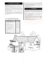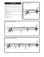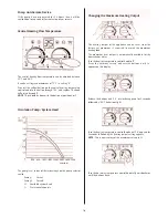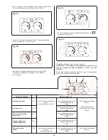
The fitting of this flue system is described later in the installation
process.
Instructions for fitting other flue systems are packed with the
relevant flue kit.
NOTE: The 125mm diameter horizontal flue system to be
used for lengths between 2m and 8m requires a
clearance of 365mm above the appliance casing.
Check that the position chosen for the appliance is satisfactory.
Unpack the appliance.
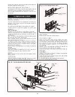
A wall mounting plate and manifold assembly are supplied in a
separate pack to allow the pre-installation connection to the
system and flushing.
(If wall mounting assembly is not assembled).
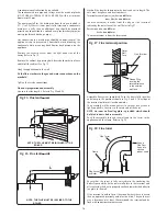
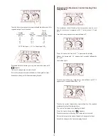
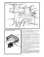
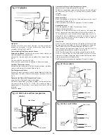
Fix the wall mounting assembly together using the screws
supplied to secure the top and bottom cross-members. Refer to
Fig.9.
Ensure that the top section has the support lugs facing upwards
and outwards.
11
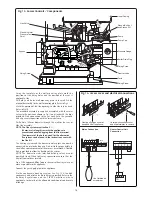
Fig. 9. Wall mounting assembly.
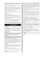
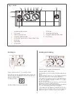
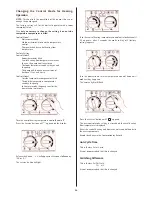
Fig. 11. Manifold connections.
Central
heating
flow
Valve
clips
Wall mounting manifold plate
Domestic
hot
water
Cold
water
inlet
Central
heating
return
Gas
30
20
10
▲
▲
▲
▲
200
▲
▲
65
65
65
65
▲
▲
▲
▲
▲
▲
▲
▲
Support
Lugs
Manifold
Assembly
Wall Mounting
Plate
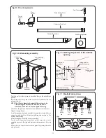
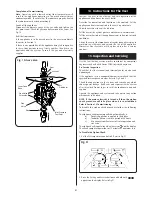
Fig. 10. Marking the position of the side flue
opening.
Appliance
115
Drilling point for
flue duct opening
2.5¡
(44mm/meter)
1 in 22
Centre
line of
flue
opening
and
appliance
H
H mm
Standard Horizontal Flue
88
Alternative Horizontal Flue
250
Centre line of
flue/air duct
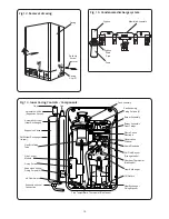
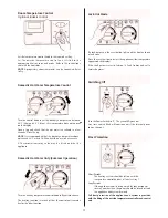
Fig. F4. Flue Components.
Flue
Turret
Turret
Clamp
Extension Air Duct
Extension Flue Duct
Terminal Assembly
Duct Clamp
Wall Sealing Plates
Top of the
wall
mounting
frame
Содержание Greenstar ZWBR 11-25 A31
Страница 31: ...31 ...

