Bosch Greenstar Series Скачать руководство пользователя страница 41

Notes on installation and operation

41

Greenstar – 6721822579 (2021/01)

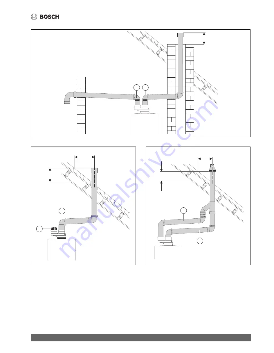
Fig. 36 Vertical venting system (sealed combustion)

Fig. 37 Vertical venting system (room air only)

Fig. 38 Vertical venting system (sealed combustion)

Key to Fig. 36, Fig. 37 and Fig. 38:

[1]

Intake

[2]

Exhaust

X

Greater than 12 inches (305 mm)

Y

Greater than 12 inches (305 mm)

6 720 641 933-09.2O

Y

1

2

6 720 641 933-07.1O

1

Y

X

2

6 720 641 933-10.1O

1

2

Y

X

Содержание Greenstar Series

Страница 1: ... certified installer or the gas supply company WARNING The operating instructions are part of the technical documents that must be handed over to the owner or operator of the heating system Explain to the owner or operator how to use the heating system using the operating instructions Make sure that they are familiar with all required information for the safe and proper operation of the heating sy...

Страница 2: ...n vessel ZBR 3A 31 6 4 Selecting the installation location 31 6 5 Pre installing pipes 32 6 6 Mounting the appliance 33 6 7 Installing the low water cut off LWCO 34 6 8 Connecting flue gas accessories 35 6 8 1 Installation of the exhaust and air intake system 36 6 8 2 Examples of approved horizontal and vertical venting installation 40 6 8 3 Vent and combustion air pipe lengths 42 6 9 Testing gas ...

Страница 3: ...suring CO content of flue gas 64 14 Environmental protection and disposal 65 15 Inspection and maintenance 65 15 1 Description of various steps 66 15 1 1 Calling up the latest fault service function 6 A 66 15 1 2 Fresh water filter only combi boiler ZWB 3A 66 15 1 3 Plate type heat exchanger only combi boiler ZWB 3A 66 15 1 4 Checking electrodes 67 15 1 5 Burner servicing 67 15 1 6 Heat exchanger ...

Страница 4: ...moke Do not use lighters Warn all occupants of the building but do not ring any bell From outside the building call the gas supply company and a trained and certified installer or service company If you smell flue gas Switch off the heating system by shutting off the emergency shut off switch Open windows and doors Call a trained and certified installer or service company DANGER Risk of fatal inju...

Страница 5: ...ems within 16 inches 415mm of the appliance CAUTION Appliance damage from contaminated combustion air Keep the combustion air free of corrosive substances e g halogenated hydrocarbons from painting operations or beauty salons Keep combustion air free from dust and lint e g from laundry or agricultural operations If clean room air is not available fresh outdoor combustion air must be provided DANGE...

Страница 6: ...pliance 3 Mounting bracket with mounting kit 4 Gas conversion kit 5 Adapter and cable grommet for connection of a LWCO Contents of package 2 6 Rail with connection box 7 Flue adapter1 8 DHW tank temperature sensor NTC 9 Hydraulics connection plate with mounting kit 10 External supply temperature sensor NTC 11 Bosch Room Controller with an integrated temperature sensor and set of documents 1 8 7 6 ...

Страница 7: ...ppliance 3 Mounting bracket with mounting kit 4 Gas conversion kit 5 Adapter and cable grommet for connection of a LWCO Contents of package 2 6 Rail with connection box 7 Flue adapter1 8 Hydraulics connection plate with mounting kit 9 External supply temperature sensor NTC 10 Bosch Room Controller with an integrated temperature sensor and set of documents 7 8 6 10 1 2 3 4 5 9 0010016623 002 1 Conc...

Страница 8: ...orted appliance 23 Natural gas NG 3 3 Rating plate The rating plate is located at the right side of the appliance Fig 3 Data plate location The rating plate contains the appliance output model number approval data and serial number 3 4 Appliance description Appliance for wall installation regardless of chimney and room size Bosch Room Controller Intelligent boiler pump control Heatronic boiler con...

Страница 9: ...complete 2 Front cover 3 Hydraulics connection plate Zero clearance from combustibles permitted but 4 102 mm recommended for serviceability Distance to door if mounted inside a closet 17 21 64 440 mm 4 102 mm 4 102 mm 3 11 32 85 mm 33 15 32 850 mm 9 29 64 240 mm 7 7 8 200 mm 33 27 64 849 mm 1 3 16 30 mm 13 57 64 353 mm 33 15 16 862 mm 4 102 mm 15 381 mm 3 1 2 0010004928 001 4 102 mm ...

Страница 10: ...tar 6721822579 2021 01 10 3 7 Appliance layout heating boiler ZBR 3A Fig 5 Appliance layout ZBR 3A min 12 13 14 16 20 18 19 17 31 33 34 36 38 40 30 29 35 28 37 39 32 27 23 22 21 26 25 24 15 6 7 11 8 9 10 2 5 4 3 1 0010016624 002 ...

Страница 11: ... limiter 17 Safety relief valve discharge hose 18 Combustion air intake 19 Exhaust pipe 20 Boiler supply pipe 21 Connection for optional low water cut off LWCO 22 Additional supply temperature limiter 23 Manual air bleeder 24 Gas air premix chamber 25 Fan 26 Bracket 27 Wall hanging bracket 28 Exhaust pipe 29 Pressure relief valve heating zone 30 Sight glass 31 Set of electrodes 32 Supply temperatu...

Страница 12: ...ar 6721822579 2021 01 12 3 8 Appliance layout ZWB 3A Fig 6 Appliance layout ZWB 3A min 12 15 16 18 19 20 21 23 22 26 29 17 27 28 31 32 33 37 38 39 34 35 36 13 14 30 24 25 44 40 41 42 43 min 6 7 11 8 9 10 2 5 4 3 1 0010016625 002 ...

Страница 13: ... gas adjuster 19 Flue gas temperature limiter 20 Safety relief valve discharge hose 21 Combustion air intake 22 Supply pipe 23 Connection for optional low water cut off LWCO 24 Additional supply temperature limiter 25 Pressure relief valve heating zone 26 Gas air premix chamber 27 Expansion vessel 28 Fan 29 Bracket 30 Wall hanging bracket 31 Exhaust pipe 32 Sight glass 33 Set of electrodes 34 Supp...

Страница 14: ...21822579 2021 01 14 3 9 Electrical wiring ZBR 3A Fig 7 Electrical wiring diagram ZBR 3A L N B B F A 6 720 641 933 23 3O 9 8 7 LZ NZ LS NS 4 2 1 2 3 6 7 4 5 8 9 L N 4 6 1 2 3 5 7 11 9 12 14 15 16 17 18 19 20 21 22 23 24 6 10 8 25 13 4 ...

Страница 15: ...water cut off LWCO 9 BUS connection e g heating control 10 Room thermostat dry contact 11 Outdoor temperature sensor 12 Code plug 13 Diagnostic interface 14 ON OFF switch 15 Gas valve 16 Fan 17 Flue gas temperature limiter 18 Supply temperature sensor 19 Flame rod electrode 20 Ignition electrode 21 Boiler block temperature limiter 22 DHW tank temperature sensor NTC 23 Boiler circulator 24 Addition...

Страница 16: ...1822579 2021 01 16 3 10 Electrical wiring ZWB 3A Fig 8 Electrical wiring diagram ZWB 3A L N B B F A 6 720 641 933 24 3O 9 8 7 LZ NZ LS NS 4 2 1 2 3 6 7 4 5 8 9 4 6 24 23 6 1 2 3 4 6 10 8 11 13 14 15 16 17 18 19 20 22 21 25 5 9 7 26 12 ...

Страница 17: ...nnection e g heating control 9 Room thermostat dry contact 10 Outdoor temperature sensor 11 Code plug 12 Diagnostic interface 13 ON OFF switch 14 Gas valve 15 Fan 16 Flue gas temperature limiter 17 Supply temperature sensor 18 Flame rod electrode 19 Ignition electrode 20 Boiler block temperature limiter 21 DHW temperature sensor 22 Boiler circulator 23 3 way valve Space heating DHW heating 24 Flow...

Страница 18: ...essure NG in W C mbar 3 5 10 5 8 7 26 1 LPG propane in W C mbar 8 13 19 9 32 3 Flue gas Flue gas mass flow at maximum minimum nominal output g s 9 4 3 2 9 2 4 8 Flue gas temperature 176 140 F 80 60 C at maximum minimum nominal heat input F C 145 133 63 56 145 133 63 56 Flue gas temperature 104 86 F 40 30 C at maximum minimum nominal heat input F C 115 90 46 32 115 90 46 32 CO2 at max nominal outpu...

Страница 19: ...10 5 8 7 26 1 LPG propane in W C mbar 8 13 19 9 32 3 8 13 19 9 32 3 Flue gas Flue gas mass flow at maximum minimum nominal output g s 12 0 3 2 11 6 4 8 15 7 4 5 15 2 5 6 Flue gas temperature 176 140 F 80 60 C at maximum minimum nominal heat input F C 147 133 64 56 147 133 64 56 162 135 72 57 162 135 72 57 Flue gas temperature 104 86 F 40 30 C at maximum minimum nominal heat input F C 117 90 47 32 ...

Страница 20: ... 30 C BTU hr kW 114 125 33 5 119 625 35 1 Max output rate 122 86 F 50 30 C BTU hr kW 114 125 33 5 119 625 35 1 Max output rate 176 140 F 80 60 C BTU hr kW 111 552 32 7 116 928 34 3 Gas connection value Natural Gas Hs 1 010 BTU ft3 37 3MJ m3 ft3 hr m3 h 149 4 2 Liquid Propane Gas HD S 2 500 BTU ft3 93 1MJ m3 ft3 hr m3 h 59 1 7 Permissible inlet gas pressure NG in W C mbar 3 5 10 5 8 7 26 1 LPG prop...

Страница 21: ... gal l 3 17 12 3 17 12 3 17 12 3 17 12 DHW Max DHW flow rate gpm l min 2 64 10 2 64 10 3 17 12 3 17 12 NominalDHWflowrate at140 F 60 C outlettemperature gpm l min 2 03 7 7 2 03 7 7 2 6 10 2 6 10 Outlet temperature F C 104 140 40 60 104 140 40 60 104 140 40 60 104 140 40 60 Max cold water inlet temperature F C 140 60 140 60 140 60 140 60 Max approved DHW pressure psi bar 150 10 3 150 10 3 150 10 3 ...

Страница 22: ...21 37 8 Max output rate 104 86 F 40 30 C BTU hr kW 114 125 33 5 119 625 35 1 Max output rate 122 86 F 50 30 C BTU hr kW 114 125 33 5 119 625 35 1 Max output rate 176 140 F 80 60 C BTU hr kW 111 552 32 7 116 928 34 3 Output rate domestic hot water DHW 113 F 45 C BTU hr kW 114 125 33 5 119 625 35 1 Output rate domestic hot water DHW 140 F 60 C BTU hr kW 112 714 33 0 118 146 34 6 Gas connection value...

Страница 23: ...quirements of the standard for Controls and Safety Devices for Automatically Fired Boilers ANSI ASME CSD 1 Install CO detectors per local regulations Wall mounted gas condensing boilers require yearly maintenance Chapter 15 page 65 4 2 Operating limits of the boiler The heat exchanger has been designed and certified in accordance with the ASME Boiler and Pressure Vessel Code Section IV Table 9 Ope...

Страница 24: ...eight of eight 8 feetabovegradedirectlyin line with the exhaust vent terminal for the horizontally vented gas0fueled heating appliance or equipment The sign shall read in print size no less than one half inch in size GAS VENT DIRECTLY BELOW DO NOT BLOCK CHECK The state or local gas inspector of the side wall horizontally vented gas fueled equipment shall not approve the installation unless upon in...

Страница 25: ...ump 9 To indirect tank 10 Comfort Zone Module CZM100 11 External system supply temperature sensor for system supply pipe to be installed in closest vicinity with boiler supply Tee 12 Boiler primary line supply pipe 1 13 Boiler primary line return pipe 1 14 Heating boiler ZBR 3A 15 From indirect tank 16 From heating zone 1 17 From heating zone 2 18 Expansion vessel X 4 pipe diameters on boiler prim...

Страница 26: ...nal 12 LWCO Low Water Cut Off 24V AC Transformer required 13 DHW temperature sensor connection with clear connector 14 Optionally connect external system supply temperature sensor for system supply pipe here with white plug For all accessories not included in the package please refer to the Bosch Product Catalog B B F A 6 720 806 992 04 2O 9 8 7 LZ NZ 4 2 L N F V L N LS NS 0 1 2 3 4 5 6 CZM100 1 2...

Страница 27: ...ating zone 1 CRC200 10 Comfort Zone Module CZM100 11 External system supply temperature sensor for system supply pipe to be installed in closest vicinity with boiler supply Tee 12 Boiler primary line supply pipe 1 13 Boiler primary line return pipe 1 14 Heating boiler ZBR 3A 15 From heating zone 1 16 From heating zone 2 17 From heating zone 3 18 Expansion vessel X 4 pipe diameters on boiler primar...

Страница 28: ...O Low Water Cut Off 24V AC Transformer required 12 DHW temperature sensor connection with clear connector 13 Optionally connect external system supply temperature sensor for system supply pipe here with white plug For all accessories not included in the package please refer to the Bosch Product Catalog B B F A 6 720 806 992 06 2O 9 8 7 LZ NZ 4 2 L N F V L N LS NS 5 4 1 13 3 2 11 10 12 9 8 7 1 2 BU...

Страница 29: ...H annually If using antifreeze fill with approved antifreeze and fresh water Always follow the cleaner antifreeze or additive manufacturer s instructions Do not mix different manufacturer s products Follow manufacturer s data to determine the anti freeze ratio for the desired freeze protection temperature Recirculation pump DHW recirculation lines Table 10 Recommended flow rates Use service functi...

Страница 30: ...fuel gas code or CAN CSA B 149 1 Natural Gas and Propane installation code Install a pressure regulator with a safety valve 6 1 2 Other important information The installation of this boiler must comply with all national and local code and regulations Only operate this boiler with the combined air flue system specifically designed and approved for it Use only approved venting systems per the manufa...

Страница 31: ...mple of installation of an external expansion vessel 6 4 Selecting the installation location Installation location requirements Observe the current national and local codes and regulations Observe country specific requirements Observe installation instructions of the venting system accessories and their clearances Combustion air To avoid corrosion keep the supply of combustion air free of corrosiv...

Страница 32: ... insufficient load capacity the appliance and the hydraulics connection plate must be mounted on a sheet of plywood or similar reinforcement Remove the mounting template Secure the hydraulics connection plate and the mounting bracket with the mounting kits supplied Fig 17 Mounting of the hydraulics connection plate and the mounting bracket Fig 18 Hydraulics connection plate for heating boiler ZBR ...

Страница 33: ... 29 Remove packaging observing all notes and symbols On the type plate check the identification of the target country and suitability for the gas type supplied by the local gas utility company page 8 Removing the cover The cover is secured with two screws against unintentional removal electrical safety Always keep the cover secured with these screws Undo screws step 1 Lift strap step 2 and remove ...

Страница 34: ...ergency shutoff switch or disengaging the heating system circuit breaker Drain the boiler Remove the safety clip from the dummy plug in the supply pipe step 1 Pull off the dummy plug step 2 and place with the boiler documentation Ensure the O ring remains in place on the pipe Lubricate the O ring Fig 23 Installing a LWCO device removing dummy plug Screw the LWCO as far as possible into LWCO adapte...

Страница 35: ...e gas adapter 1 Vent flange 2 Flue gas adapter 3 Combustion air test port 4 Flue gas test ports Tighten the screws To avoid premature wear of the gaskets DO NOT use lubricants In case of open venting Use basket on the air intake In case of concentric venting system As an alternative to twin pipe venting a purposely designed and built telescopic concentric vent kit can be obtained as an accessory f...

Страница 36: ...ts Adhere to national code requirements Observe the listed maximum lengths of vent system which are boiler model dependent chapter 6 8 3 DANGER Improper venting of the Greenstar boiler can result in excessive levelsofcarbonmonoxidewhichcanresultinseverepersonalinjury or death The boiler must be vented in accordance with the Venting of Equipment section of the latest edition of ANSI Z 223 1 NFPA 54...

Страница 37: ... comply with the following Table 14 Materials for pipe Material Item United states Canada ZBR 21 3 A ZBR 28 3 A ZBR 35 3 A ZBR 42 3 A ZWB 28 3 A ZWB 35 3 A ZWB 42 3 A PVC schedule 40 80 2 50 mm Vent or air pipe and fitting ANSI ASTM D1785 or UL 1738 BH Gas venting systems ULC S636 a Class IIA PVC Class IIB CPVC Class IIC Polypropylene certified to ULC S636 a Components of the certified vent system...

Страница 38: ... Ø 80 125 mm concentric PP M G Duravent PolyPro and Centrotherm InnoFlue 3PPS VK TC M G Duravent or ICRT3539 Centrotherm Ø 3 Ø 80 mm with base support PolyPro Flex Chimney Cap PP PolyPro Support Elbow Base Support SW to Flex Coupler M G Duravent PolyPro Centrotherm InnoFlue M G Duravent PolyPro Centrotherm InnoFlue 3PPS FCT ISCP03 3PPS SE90X ISBS0387 IFSFC03 Ø 2 Ø 50 mm with base support PolyPro F...

Страница 39: ... YA At least 1 foot 305 mm above grade or snow line YB Exhaust terminal must be at least 3 feet 915 mm above forced air inlet within 10 feet 3050 mm horizontally USA 6 feet 1830 mm above forced air inlet Canada X 1 X2 X3 X 4 X 5 X 1 X 1 X2 X 3 X3 1 2 Y A Y B Y A 6 720 641 933 17 1O 3 3 3 3 1 For Clearances not specified in ANSI Z223 1 NFPA 54 or CSA B149 1 Clearance in accordance with local instal...

Страница 40: ... adversely affected by flue gases Wheninstallingseveralappliancesinarow maintainaclearanceofat least 1 ft 305 mm between the vent terminal of one appliance and the combustion air inlet of the next appliance Fig 32 Horizontal venting system room air only Fig 33 Horizontal venting system room air only Key to Fig 32 and Fig 33 1 Intake 2 Exhaust Fig 34 Horizontal venting system sealed combustion Fig ...

Страница 41: ...ed combustion Fig 37 Vertical venting system room air only Fig 38 Vertical venting system sealed combustion Key to Fig 36 Fig 37 and Fig 38 1 Intake 2 Exhaust X Greater than 12 inches 305 mm Y Greater than 12 inches 305 mm 6 720 641 933 09 2O Y 1 2 6 720 641 933 07 1O 1 Y X 2 6 720 641 933 10 1O 1 2 Y X ...

Страница 42: ... combustion air pipe length is 100 feet each with no more than 8 elbows each 2 50 mm Vent and combustion air pipe The maximum total combined equivalent length of vent and combustion air pipe tab 17 18 and 19 depend on the installation situation the appliance type and number of elbows used Table 17 Vent and combustion air pipe lengths with 2 diameter and separate terminations 2 6 720 641 933 08 1O ...

Страница 43: ...ctions for leakage test pressure Max 30 psi 2 07 bar on the pressure gauge Gas line Close the gas shutoff valve to protect the gas valve from damage Check all connections for leakage test pressure Max 60 W C 150 mbar Release pressure Installations Fig 35 Stainless steel wall termination 2 PIPE Maximum straight vent pipe length allowed for Ø 2 pipe Number of 90 elbows used ZBR 21 3A ZBR 28 3A ZWB 2...

Страница 44: ...st AWG14 size cables All appliance modulation control and safety components are tested and pre wired for use Observe safety precautions and all rules and regulations required by local code and the National Electric Code Fuses The appliance is protected with a fuse It is located on the circuit board Fig 8 page 16 Replacement fuses can be found on the back of the cover Fig 43 page 44 Controls and mo...

Страница 45: ...m Punch out plastic insert Plug connector into the circuit board Insert the cable of the DHW tank temperature sensor Secure the cable with the strain relief Fig 47 Electrical connections DHW tank temperature sensor 7 2 5 Connecting additional accessories For splash protection IP always cut the strain relief to match the diameter of the cable Fig 48 Cut off grommets Feed cable through strain relief...

Страница 46: ...imary line return pipe 1 5 System secondary line return pipe Fig 51 Electrical wiring of external supply temperature sensor The service function 7 d connection of an external supply temperature sensor is automatically set to 01 page 60 Connecting Third party room thermostats or zone controls Avoltagefree drycontact thirdpartyroomthermostatorheatdemand from a relay panel can be used to send an ON O...

Страница 47: ... pump to appliance Insert cable into the junction box as shown in Fig 55 Connect cable to the black plug according to Fig 54 Fig 54 Attach plug external pump 1 L 120 VAC 60 Hz 2 PE GND Ground 3 N Neutral 4 Black plug in the junction box upon delivery Connect black plugs and insert grommet until stop Fig 55 Cable connected external pump Use service function 5 E to set connection to 01 DHW recircula...

Страница 48: ...tank loading when energized Use service function 1 F to set pump mode page 57 7 3 4 Connecting mains power supply Route the power cable AC 120 V 60 Hz from the emergency shutoff switch to the boiler Insert cable into the junction box as shown in Fig 59 Connect cable to the white plug according to Fig 58 Fig 58 Attach plug mains power supply 1 L 120 VAC 60 Hz 2 PE GND Ground 3 N Neutral 4 White plu...

Страница 49: ...of the cable grommet Fig 60 Mounting the cable grommet included in scope of delivery Install a 24 VAC 20 VA transformer near the boiler Follow LWCO manufacturer s instructions Connect the lead labeled BOILER GROUND green to pin 2 center of the white plug in the junction box of the wall mounted gas condensing boiler Connect the two leads labeled 24 V HOT red and 24 V COMMON white to the external 24...

Страница 50: ...7 Reset button 8 Display 9 Automatic air vent ZWB 3A combi boilers only 10 Boiler water pressure gauge 11 DHW thermostat 12 Safety relief valve discharge hose 13 Condensate drain hose 14 Heating return pipe 15 Cold water pipe ZWB 3A combi boilers only 16 Gas pipe 17 DHW pipe ZWB 3A combi boilers only 18 Supply pipe 19 Boiler high limit dial eco reset 1 2 3 4 5 6 7 8 9 11 10 12 13 15 16 18 19 14 6 ...

Страница 51: ...ng zone pump switching on and off at intervals for approx 4 minutes The display shows in alternation with the supply temperature Open the automatic vent 9 only ZWB 3A and close it again when the purging sequence has finished page 50 If the display shows in alternation with the supply temperature the trap filling function is active page 59 Shutdown Switch appliance OFF using the ON OFF switch The d...

Страница 52: ...tion page 54 If there is reason for concern for contamination from bacteria such as legionella consider setting the DHW thermostat to at least e 131 F 55 C This setting ensures an economical and comfortable DHW generation Consult your local water department or municipality for further information ECO button The default setting is DHW priority the ECO button is not lit In order to switch between DH...

Страница 53: ...f freezing In manual summer mode only the appliance is protected from freezing Observe frost protection measures where there is a risk of frost chapter 8 9 Note the supply temperature controller setting Turn the boiler highlimit dial counterclockwise as far as itwill go Fig 68 Summer mode For further information see the operating instructions for the heating control included in the scope of delive...

Страница 54: ... heating control with DHW program Set any DHW recirculation pump to continuous operation Turn DHW thermostat clockwise to max approx 158 F 70 C Fig 72 Thermal disinfection Wait until the maximum temperature has been reached Open all DHW taps from the nearest to the one furthest away and draw off hot water until it reaches a minimum of 158 F 70 C at all taps for at least 3 minutes Reset the DHW the...

Страница 55: ... such as 1 A first service level Repeatedly press the key pad lock button or ECO button to scroll to the desired service function Press and release the emissions test button The chimney sweep button lights up and the display shows the setting for the selected service function Adjust Value Repeatedly pressthekey padlock buttonor ECObuttontoadjust the value up or down Record the value in the commiss...

Страница 56: ...erature 57 2 C Purging function 57 2 d Thermal disinfection 57 2 F Operating mode 58 3 A Automatic anti cycle function 58 3 b Set anti cycle time 58 3 C Switching differential hysteresis 58 3 d Minimum output heating and DHW 58 3 E Cycle time keeping DHW hot 58 3 F Constant DHW period 59 4 b Maximum heat exchanger temperature 59 4 d Audible fault warning tone 59 4 E Appliance type 59 4 F Condensat...

Страница 57: ...e after the low loss header In DHW mode DHW tank loading pump runs In space heating mode DHW tank loading pump does not run Default setting is 03 Service function 2 A Heating circuit pump lockout time only heating boiler ZBR 3A NOTICE System damage or boiler malfunction Never change the setting of this service function on combi boiler ZWB 3A appliances ThissettingisonlyactiveifServicefunction1 F P...

Страница 58: ...ion be active If an outdoor reset control is connected there is no need to adjust this setting on the appliance The control automatically optimizes the anti cycle time The anti cycle time can be set from 00 to 15 0 to 15 minutes With 00 the anti cycle lock is switched off The shortest possible switching interval is 1 minute recommended for single zone or forced air heating systems Default setting ...

Страница 59: ... reactivate the trap filling function The trap filling sequence ensures that the condensate trap is filled after initial installation or after a longer downtime of the appliance The trap filling sequence is activated if The appliance is switched OFF using the ON OFF switch The burner has not been in use for at least 28 days You are switching between summer and winter mode The next time there is a ...

Страница 60: ...cted by default you do not need to change any settings Ifasensorisdisconnected changethesettingbacktothedefaultsetting 00 The following settings are available 00 Once only automatic detection of a sensor 01 External supply temperature sensor connected to Heatronic 02 External supply temperature sensor connected to CZM100 Default setting is 00 Service function 7 E Building drying function This serv...

Страница 61: ...tion 9 b Current fan speed This service function allows you to display the current fan speed in revolutions per second 1 s Service function 9 C Current boiler output This service function displays the current boiler output in percent Service function 9 d Set fan start speed At higher elevations the boiler fan may need to spin faster upon startup to ensure reliable ignition every time The start spe...

Страница 62: ...before working on parts that carry gas Replace used seals with new seals After completing the work on parts that carry gas carry out a leak test A gas conversion kit with instructions for gas conversion is included in the scope of delivery Follow the instructions from the conversion kit With the gas conversion kit there is no setting of the gasair ratio CO2 or O2 necessary 12 2 Installation locati...

Страница 63: ...Fig 79 3 fromthegasvalveadjustmentscrew Fig 79 2 and set CO2 or O2 value for minimum nominal output Fig 79 Setting the CO2 or O2 values for minimum nominal output Re check settings at maximum and minimum nominal output and re adjust if necessary Repeatedly press the emissions test button until the light goes out The display returns to the supply temperature Record the CO2 or O2 levels and the CO c...

Страница 64: ...ons test button The following appliance outputs can be selected by pressing the emissions test button until it lights up Fig 82 Press the emissions test button Maximum set output in heating mode Maximum heating output page 56 maximum nominal output Minimum nominal output You have 15 minutes to complete the tests After that the appliance returns to default mode 13 2 Measuring CO content of flue gas...

Страница 65: ...Always disconnect the appliance from the mains power before performing any work Take measures to prevent accidental reconnection NOTICE Insufficient antifreeze can accelerate corrosion Frost protection level has to be checked annually during the regular scheduled maintenance of the condensing boiler Heat exchanger NOTICE Damage to the coating of the heat exchanger Cleaning of the heat exchanger sh...

Страница 66: ...cantly reduced Check filter in the cold water pipe for contamination page 66 Depressurize the appliance Remove plate type heat exchanger and replace or Descale with descaling agent approved for stainless steel Grade 316 1 4401 To remove the plate type heat exchanger Unplug electrical connections Remove hose from safety relief valve Fig 84 Unplugging electrical connections removing hose from safety...

Страница 67: ...tall electrode set with new gaskets and check for leaks Fig 89 Reinstalling the electrode set Fig 90 Check for leaks 15 1 5 Burner servicing DANGER Fire danger The burner may be operated only while installed in a wall mounted gas condensing boiler Remove burner lid steps 1 4 Fig 91 Removing the burner cover Remove burner and clean its components Fig 92 Burner Reinstall burner in reverse order incl...

Страница 68: ...exchanger through visual inspection If mechanical cleaning is required Tocleanoftheheatexchanger useBoschburnergaskets cleaningbrush kit and cleaning blade all of which are available as spare parts Remove the condensate trap steps 1 and 2 and place a suitable container underneath Fig 93 Removing the condensate trap With the cleaning blade clean the heat exchanger block from the bottom to the top F...

Страница 69: ...ensate trap Remove condensate trap steps 1 and 2 and check heat exchanger orifice for clear passage Fig 98 Removing the condensate trap Remove and clean the condensate trap lid Check condensate hose and clean if necessary Fill the condensate trap with approx 1 cup 1 4 l of water and reinstall it 15 1 8 Checking the mixer diaphragm Open the mixer unit Carefully remove the diaphragm from the fan air...

Страница 70: ...e of the system water and analyze pH using a pH meter or pH test strips Table 32 Waterpreparationforfillingandmaintainingtheheatingsystem pH value If the value is outside of the permitted range drain the system flush and refill with fresh water to prevent system damage or leaks If the fill water does not meet the requirements of page 29 treat the water to bring it within the permissible range If a...

Страница 71: ...of the combustion air pipes and vent pipes 4 Dynamic gas pressure inches W C mbar 5 Gas air ratio at min max nominal output min max 6 Gas and water side leak test 7 Inspect electrodes 8 Inspect heat exchanger block 9 Check burner 10 Inspect diaphragm in mixer unit 11 Clean condensate trap 12 With the system depressurized check the expansion vessel pre charge pressure vs the static head of the heat...

Страница 72: ... button and holding longer than 3 seconds Save function The display shows the supply temperature in alternation with The appliance works for 15 minutes at the minimum nominal output service function 2 F The display shows the supply temperature in alternationwith Theapplianceworkswiththeset maximum output in heating mode service function 1 A The display shows the supply temperature alternating with...

Страница 73: ...is not possible protect your heating system from freezing by draining the heating system and hot water pipes at the lowest point NOTICE The Heatronic boiler control can be damaged by leaking water Cover the Heatronic prior to work on water filled components TheHeatronicboilercontrolmonitorsallsafetyandcontrolcomponents If a fault arises during operation an audible warning tone sounds Press a butto...

Страница 74: ...ature sensor and leads for interruptions or shorts and replace if defective Temperature guard TB1 has tripped Check if jumper across 8 9 or PR P0 is missing Reset external temperature limiter if installed Reset LWCO if installed Reset pressure regulator if installed d5 External supply temperature sensor defective low loss header The external supply temperature sensor was recognized on the BUS and ...

Страница 75: ...l plug in contacts and ignition leads replace PCB if defective Check gas air ratio correct if out of specification F1 Internal data error Reset boiler to the factory default setting service function 8 E F7 Flame detected even when burner is off Check electrodes replace if defective Check flue gas system clean or repair if defective Check PCB for moisture dry if needed FA After switching gas off Fl...

Страница 76: ...sure adjust if defective Check power supply Check electrodes for visual damage replace if defective Check flue gas system clean or repair if defective Check gas air ratio replace gas valve if defective Check gas valve replace if defective Check burner replace if required DHW has unpleasant odor or has a dark color Perform thermal disinfection of the DHW circuit Replace sacrificial anode in the tan...

Страница 77: ...ce 10 Resistance 32 0 33 555 50 10 21 232 68 20 13 779 86 30 9 128 104 40 6 205 122 50 4 298 140 60 3 025 158 70 2 176 176 80 1 589 194 90 1 177 212 100 886 Temperature F C Testing tolerance 10 Resistance 68 20 14 772 77 25 11 981 86 30 9 786 95 35 8 047 104 40 6 653 113 45 5 523 122 50 4 608 131 55 3 856 140 60 3 243 149 65 2 744 158 70 2 332 167 75 1 990 176 80 1 704 185 85 1 464 194 90 1 262 20...

Страница 78: ...l output Notes regarding under or overpressure operation Gas setting and flue gas test Set gas type Inlet gas pressure W C mbar Gas static supply pressure W C mbar Selected maximum output MBH kW Selected minimum output MBH kW Gas flow rate at maximum nominal output gpm l min Gas flow rate at minimum nominal output gpm l min Net calorific value HiB per gas supplier MBTU ft3 kWh m3 CO2 at max nomina...

Страница 79: ...check carried out Leak test carried out on the gas and water sides Commissioning includeschecking the settings avisual heatingleak testandafunctionalcheck oftheboiler and control The system installerconducts a test of the heating system The system named above has been checked to the extent described ___________________________________________________________ Name of service engineer The documents ...

Страница 80: ...552 1100 Fax 603 965 7581 www bosch climate us U S A Products manufactured by Bosch Thermotechnik GmbH Junkersstrasse 20 24 D 73249 Wernau www bosch thermotechnology com Bosch Thermotechnology Corp reserves the right to make changes without notice due to continuing engineering and technological advances ...

Отзывы: