EN
Installation Instructions
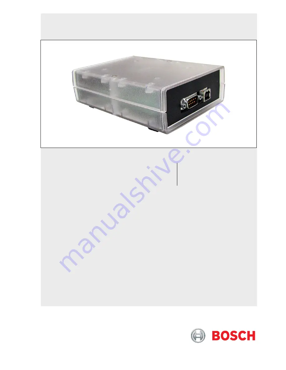
RS-232/USB Serial Interface Module
DX4010V2
Страница 1: ...EN Installation Instructions RS 232 USB Serial Interface Module DX4010V2 ...
Страница 2: ...llation Instructions Trademarks 2 Bosch Security Systems Inc 9 08 F01U083036 01 Trademarks BlackBox is either a registered trademark or a trademark of BlackBox Corporation in the United States and or other countries ...
Страница 3: ...al Device Connections 5 Figure 5 Parallel Device Connections 6 Figure 6 P2 Jumper Settings 6 Figure 7 DIP Switch Location and Orientation 7 Figure 8 DB9 Connector Layout 10 Figure 9 P3 Connector 11 Figure 10 Select File 11 Figure 11 Security Warning 11 Figure 12 Install Shield 11 Figure 13 Security Warning 11 Figure 14 Destination Location 12 Figure 15 Ready to Install 12 Figure 16 Setup Status 12...
Страница 4: ...lative Humidity 5 to 85 30 C 86 F non condensing Control Panel Compatibility Option bus control panels D6412 D4412 DS7240 DS7220 DS7400Xi v2 02 or higher SDI bus control panels v6 0 or higher D9412GV2 D7412GV2 D7212GV2 D9412G D7412G D7212G D9124 D9112 D7412 and D7212 Table 1 DX4010V2 Specifications continued Application Compatibility RPS Supported on all compatible control panels PC 9000 Supported...
Страница 5: ...g is limited to 305 m 1000 ft Connect the DX4010V2 to the control panel data and auxiliary power sources as shown in Figure 2 Figure 2 Control Panel Connections 1 2 3 4 5 6 B G Y R 1 DX4010V2 data bus 2 Control panel data bus 3 Option AUX common SDI common black 4 Option data SDI B green 5 Option data SDI A yellow 6 Option AUX power SDI power red If an external 12 VDC power supply is used wire as ...
Страница 6: ...ug across the jumper pins labeled P2 Refer to Figure 6 for jumper pin settings The DX4010V2 draws more current when the diagnostic LEDs are enabled Do not enable the diagnostic LEDs under normal operating conditions Figure 6 P2 Jumper Settings 3 4 1 SER Rx Tx BUS Rx Tx LED P2 P3 2 DB9 GND ENABLE P1 1 DB9 GND enable pins P1 2 Diagnostic LED enable pins P2 3 Disabled 4 Enabled Table 2 Diagnostic LED...
Страница 7: ...1 2 3 4 5 6 1 2 4 8 16 32 7 8 64 128 2 3 4 SER Rx Tx BUS Rx Tx LED P2 P3 1 DB9 GND ENABLE P1 1 Address DIP switches 2 Address example option bus Address 0 3 OFF position 4 ON position 6 0 Remote Programming Direct Connection The DX4010V2 can be used to create a local direct connection for remote programming of a compatible control panel Option Bus Set the address DIP switches to Address 0 Refer to...
Страница 8: ...N OFF 10 ON OFF ON OFF ON OFF ON OFF 11 OFF OFF ON OFF ON OFF ON OFF 12 ON ON OFF OFF ON OFF ON OFF 13 OFF ON OFF OFF ON OFF ON OFF 14 ON OFF OFF OFF ON OFF ON OFF 15 OFF OFF OFF OFF ON OFF ON OFF 134 ON ON OFF ON ON ON ON ON 135 OFF ON OFF ON ON ON ON ON 136 ON OFF OFF ON ON ON ON ON 137 OFF OFF OFF ON ON ON ON ON 138 ON ON ON OFF ON ON ON ON 139 OFF ON ON OFF ON ON ON ON 140 ON OFF ON OFF ON ON ...
Страница 9: ... OFF OFF OFF OFF 85 OFF ON OFF ON OFF OFF OFF OFF 86 ON OFF OFF ON OFF OFF OFF OFF 87 OFF OFF OFF ON OFF OFF OFF OFF 88 ON ON ON OFF OFF OFF OFF OFF 89 OFF ON ON OFF OFF OFF OFF OFF 8A ON OFF ON OFF OFF OFF OFF OFF 8B OFF OFF ON OFF OFF OFF OFF OFF 8C ON ON OFF OFF OFF OFF OFF OFF 8D OFF ON OFF OFF OFF OFF OFF OFF 8E ON OFF OFF OFF OFF OFF OFF OFF 8F OFF OFF OFF OFF OFF OFF OFF OFF Positions 5 6 a...
Страница 10: ...cable is required Consult the operating manual provided with your compatible device for wiring requirements If you are using an alternate configuration you must make a custom cable refer to Figure 8 and Table 5 Figure 8 DB9 Connector Layout 1 2 3 4 5 6 7 8 9 1 DCD 2 RxD 3 TxD 4 DTR 5 GND 6 DSR 7 RTS 8 CTS 9 RI Table 5 Alternate Wiring Configuration DX4010V2 9 Pin DTE Connector DCE 9 pin DTE 9 pin ...
Страница 11: ...240 or the GV2 control panels If no data bus header is present use the RJ 16 to spade lugs for terminal strip connections 9 0 USB Data Bus Connector Uses a standard USB type A B cable One cable is provided with the DX4010V2 If the computer does not recognize the USB port add the drivers located on the supplied disk 9 1 Installing USB Drivers Install the drivers 1 Double click CP210x_VCP_Win2K_XP_S...
Страница 12: ...6 Click Install Figure 15 Ready to Install 7 The drivers install Figure 16 Setup Status 8 Select Launch the CP210x VCP Driver Installer then click Finish Figure 17 Installation Complete 9 Click Install Figure 18 USB Driver Installer 10 The program will look for the file location Figure 19 Scanning 11 When the installation completes successfully click OK Figure 20 Installation Complete ...
Страница 13: ...s Control Panel then double click System 2 Select the Hardware tab 3 Click Device Manager Figure 21 System Properties 4 Expand Ports 5 Note the COM port number in parentheses after Silicon Labs CP210x USB to UART Bridge In this example the COM port number is 3 Figure 22 Device Manager 6 Select Enhanced Direct from the Connect Via drop down menu 7 Enter the COM Port number from Step 5 in the Com Po...
Страница 14: ... 2008 Bosch Security Systems Inc F01U083036 01 Bosch Security Systems Inc 130 Perinton Parkway Fairport NY 14450 9199 800 289 0096 ...