background image

Bosch Security Systems | 2004-11 

DVR1A1081

 | Installation Manual | Chapter 2

EN

 | 9

2.4 Interconnections

The DVR can be connected to a wide range of 
multiplexers, quads or directly to a camera.

2.4.1  Multiplexers

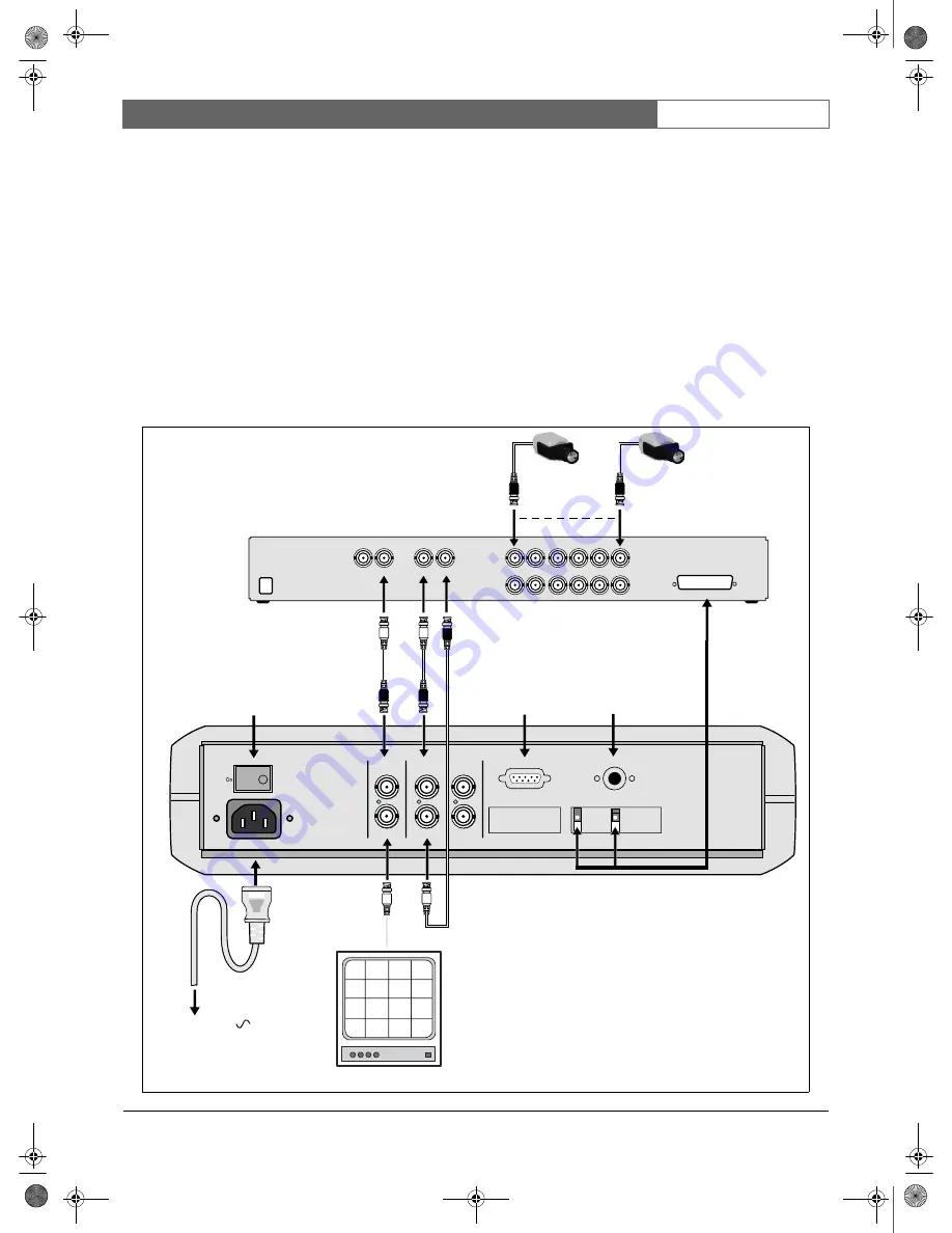
The drawing below shows how to connect a multiplexer 
to the DVR. 

Connect the monitor to the BNC socket marked 
Monitor Out on the rear of the DVR.

Connect the main monitor output of the multiplexer 
to the BNC socket marked Monitor In on the rear of 
the DVR.

Connect the VCR output of the multiplexer to the 
BNC socket marked Video In on the rear of the 
DVR.

Connect the VCR input of the multiplexer to the 
BNC socket marked Video Out on the rear of the 
DVR.

To synchronise switching with the multiplexer 
connect the VEXT and GND connections on the 
rear of the unit to the connector of the multiplexer.

When the connections are made, refer to the system 
menu to select the type of multiplexer you are using. 

Off

Power

AC 100-240

Monitor Out

Out 1

Out 2

Looping out

RS 232

Remote Control

GND

ALM

-N

C

ALM

-N

O

ALM

-C

O

VE

X

T

DISKFU

L

L

NC

3

NC

4

GND

In

Video

Monitor In

Mux main

GND

ALM

-I

N

ALM

-R

S

T

RE

C

NC

1

NC

2

GND

100-240 Vac

MON B MON A

VCR IN

VCR OUT

1

2

3

4

5

6

VEXT

GND

Power switch

RS-232 

connector

IR remote 

control eye 

connector

Multiplexer

Monito

r Out

Cameras

Monitor

VCR

Monitor

EazeoRecorderInstalA.book  Page 9  Tuesday, November 23, 2004  3:47 PM

Содержание DVR1A1081

Страница 1: ...instalacji Cyfrowy magnetowid PL Instruções de Instalação Gravador Digital PT Installation Instructions Digital Recorder EN Manuel d installation Enregistreur numérique FR Installationshandbuch Digital Recorder DE Manual de instalación Grabador digital ES EazeoRecorderInstalA book Page 1 Tuesday November 23 2004 3 47 PM ...

Страница 2: ...ENGLISH 3 FRANÇAIS 23 DEUTSCH 43 ESPAGÑOL 63 NEDERLANDS 83 ITALIANO 103 PORTUGUÊS 123 POLISH 143 EazeoRecorderInstalA book Page 2 Tuesday November 23 2004 3 47 PM ...

Страница 3: ... 4 2 Quads 10 2 4 3 Single camera 11 2 5 REMOTE CONTROL UNIT 12 3 OPERATION 13 3 1 INSTANT RECORDING 13 3 2 ALARM RECORDING 13 3 2 1 Pre alarm recording 13 3 3 NORMAL PLAYBACK 13 3 4 SEARCH PLAYBACK 13 3 5 COPY 14 3 5 1 Still image copy 14 3 5 2 Copy to movie file 14 3 6 SECURITY LOCK SETTING 14 4 MENU SET UP 15 4 1 MAIN MENU 15 4 2 CLOCK LANGUAGE MENU 15 4 3 NORMAL RECORD MENU 15 4 4 ALARM RECORD...

Страница 4: ...1 Installation Manual Table of Contents EN 4 5 SPECIFICATIONS 19 5 1 RS 232 INTERFACE 19 5 1 1 RS 232 control protocol 19 5 2 RECORDING TIME 20 5 3 TECHNICAL SPECIFICATIONS 21 EazeoRecorderInstalA book Page 4 Tuesday November 23 2004 3 47 PM ...

Страница 5: ...l with VDE 0620 connector approval by VDE 0625 minimum 10A power cord H05VV F or VW 1 0 75 mm2 x 3G should be used 12 13 The back of the recorder should only be removed by qualified maintenance and service personnel 14 Danger of explosion if battery is incorrectly replaced A lithium battery is located inside the enclosure of this recorder Replace only with the same or equivalent type Dispose of th...

Страница 6: ...k to a representative please contact the Bosch Security Systems location nearest you or visit our web site at www boschsecuritysystems com 2 Introduction The DVR1A1081 Digital Video Recorder provides advanced recording and playback technology for CCTV systems The DVR allows uninterrrupted recording in either continuous or time lapse modes for as long as a week or more There are no video tapes to c...

Страница 7: ...tle Ring to move the picture slowly forward or reverse Jog Dial In playback mode turn Jog Dial to select the playback speed In pause mode turn Jog Dial to move forward or backward image by image In menu mode turn Jog Dial to navigate through the menu pages or to select data values Use together with the ENTER key to set menu values ENTER Press to confirm a selection or a changed data value MENU Pre...

Страница 8: ...his pin starts recording When the signal drops to low recording stops NC1 NC2 No connections Signal switching voltage High 2 Vdc switching voltage Low 0 5 Vdc max input voltage 12 Vdc The alarm output signals are GND Ground connection ALM NC When an alarm occurs the connection between this pin and ALM COM is open Otherwise it is closed ALM NO When an alarm occurs the connection between this pin an...

Страница 9: ...e VCR input of the multiplexer to the BNC socket marked Video Out on the rear of the DVR To synchronise switching with the multiplexer connect the VEXT and GND connections on the rear of the unit to the connector of the multiplexer When the connections are made refer to the system menu to select the type of multiplexer you are using Off Power AC 100 240 Monitor Out Out 1 Out 2 Looping out RS 232 R...

Страница 10: ... rear of the DVR In the system menu set the multiplexer item to Off To connect a quad with a VCR output refer to the multiplexer connections Off Power AC 100 240 Monitor Out Out 1 Out 2 Looping out RS 232 Remote Control GND ALM NC ALM NO ALM CO VEXT DISKFULL NC3 NC4 GND In Video Monitor In Mux main GND ALM IN ALM RST REC NC1 NC2 GND 100 240 Vac Video OUT 1 2 3 4 VEXT GND Power switch RS 232 connec...

Страница 11: ...e BNC socket marked Video In on the rear of the DVR In the system menu set the multiplexer item to Off Off Power AC 100 240 Monitor Out Out 1 Out 2 Looping out RS 232 Remote Control GND ALM NC ALM NO ALM CO VEXT DISKFULL NC3 NC4 GND In Video Monitor In Mux main GND ALM IN ALM RST REC NC1 NC2 GND 100 240 Vac VEXT GND Power switch RS 232 connector IR remote control eye connector Camera Video Out Mon...

Страница 12: ... STOP Press to stop recording or playback PLAY Press to start playback SEARCH Increase the speed by 2x 4x 8x 16x 32x 640x 2x REWIND In playback mode press to reverse playback Search key increases reverse speed STEP REW Press to stop playback Press again to step backward image by image STEP FORW Press to stop playback Press again to step forward image by image FORWARD In reverse playback press for ...

Страница 13: ...D normal play speed 2x 4x 8x 16x 32x 640x Reverse Playback Press PLAY key to start playing back Turn the Shuttle Ring counterclockwise and fast reverse playback starts The speed is shown on the OSD normal play speed 2x 4x 8x 16x 32x 640x Slow Forward Playback Press Pause key to freeze the playing back picture Turn the Shuttle Ring clockwise and slow forward playback starts The speed is shown on th...

Страница 14: ... playing back Press the Pause key to freeze the picture Turn the Jog Dial clockwise or counterclockwise to move to the desired image Press the Copy key to enter the copy mode Turn the Jog Dial to select the desired camera image While the image is displayed press the Copy key again The message Copying appears on the screen during the process The message Success and the file identification appears o...

Страница 15: ... to 25 30 IPS QUALITY There are six quality levels for recording LOWER 15 KB LOW 20 KB BASIC 25 KB STANDARD 30 KB HIGH 35 KB SUPERIOR 40 KB RECORD TIME Shows an estimate of the recording time available on disk for the selected speed and quality 4 4 Alarm record menu ALARM OPERATION ON Record when alarm occurs OFF Do not record when alarm occurs RECORD SPEED Recording speed for the duration of the ...

Страница 16: ... SPEED When SPEED FORMAT set by HOUR the recording speed can be set from 4 6 NTSC PAL HR to 960HR When SPEED FORMAT set by IPS the recording speed can be set from 0 1 30 0 1 25 NTSC PAL IPS QUALITY There are six recording picture quality levels LOWER 15 KB LOW 20 KB BASIC 25 KB STANDARD 30 KB HIGH 35 KB SUPERIOR 40 KB SET Set ON when using timer recording Set OFF when not using timer recording In ...

Страница 17: ...through to the MONITOR OUT when the recorder is not in MENU mode UNKNOWN Select if your multiplexer is not listed and you don t have a custom code CUSTOM Select if you have a custom code for your multiplexer model Enter the parameters in the CUSTOM MULTIPLEXER PARAMETER menu PARAMETER PAIR In the CUSTOM MULTIPLEXER menu you can fill in a custom code for a particular model of multiplexer Consult yo...

Страница 18: ... the system After the system is updated successfully be sure to reset the power to activate LOAD DEFAULT Press Enter to load the factory default or not YES The confirmation dialog box appears on the screen Select Yes or No and then press ENTER CF FORMAT YES will format the Compact Flash card NO will not format the Compact Flash card 4 9 Password menu When password protection is enabled a password ...

Страница 19: ...ads in the front panel The 30 ASCII commands are shown on the following table Pin Pin DVR1C1161 HOST 1 NC 1 NC 2 TXD 2 RXD 3 RXD 3 TXD 4 NC 4 DTR 5 GROUND 5 GROUND 6 NC 6 DSR 7 NC 7 RTS 8 NC 8 CTS 9 5V 9 NC ASCII CODE FUNCTION Keypad in front panel K01 Start Recording REC K03 Stop Recording and Playing back STOP K04 Playing back PLAY K05 Pause the playback picture PAUSE K06 Search playback SEARCH ...

Страница 20: ...11 533 427 356 305 267 1 6 120 948 711 569 474 406 356 1 0 168 1481 1111 889 741 635 556 0 5 240 2963 2222 1778 1481 1270 1111 0 2 480 7407 5556 4444 3704 3175 2778 0 1 960 14815 11111 8889 7407 6349 5556 NTSC Recording Rate IPS Recording Speed Hour Picture Quality average file size Lower 15KB Low 20KB Basic 25KB Standard 30KB High 35KB Superior 40KB Approximate Recording Time Hours weeks 60 3 25 ...

Страница 21: ...o loss detection Yes Power loss detectionYes Alarm log Yes User interface Menu driven Setup By on screen display menu User input device Front panel keypad remote control IR with wired receiver optional Image export Built in Compact Flash slot for Type I and Type II cards Security Password protection Power supply 100 240 Vac 50 60 Hz Power consumption 40 W Timer Weekly timer built in real time cloc...

Страница 22: ...Bosch Security Systems 2004 11 DVR1A1081 Installation Manual Chapter 5 EN 22 EazeoRecorderInstalA book Page 22 Tuesday November 23 2004 3 47 PM ...

Отзывы: