background image

D8125 | Installation and Operation Guide | 4.0  Installation 


26 

Bosch Security Systems B.V. | 2020.04 |F01U036298-15 


4.3.6  POPIT Displays 
The status of each POPIT Module is transmitted to 

the D8112G1/G2 control panel. The status is 

recorded and held in the D8112G1/G2 memory buffer 

until the system is armed and the exit delay time has 

expired. The D1252A Keypad displays both the 

current status and the event memory with a special 

code.  
 
4.3.6.1 

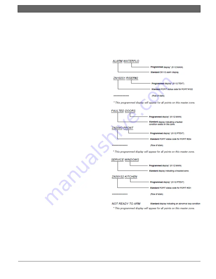
Alarm Condition Displays 

When an event occurs in the system (an open or 

shorted loop) that the D8112G1/G2 interprets as an 

alarm, the system initiates an alarm response, and the 

D1252A sequences through the following displays: 


4.3.6.2 

Fault Condition Displays 

When a loop fault occurs, the following displays can 

appear on the D1252A (rows of stars separate 

displays pertaining to individual points of protection): 


4.3.6.3 

Trouble Condition Displays 

When a loop trouble occurs, the following displays 

can appear on the D1252A (rows of stars separate 

displays pertaining to individual points of protection): 


Содержание D8125

Страница 1: ...EN Installation and Operation Guide POPEX Module D8125 ...

Страница 2: ... 11 4 2 2 Disconnecting the Battery and Transformer 11 4 2 3 Wiring Procedure 11 4 2 4 Wiring POPITs to the Data Expansion Loop 12 4 2 5 Wiring Data Expansion Loops to POPEX Modules 13 4 2 6 POPIT Sensor Loops 13 4 2 7 POPIT Module Point Assignments 15 4 3 D8112G1 G2 15 4 3 1 Wiring to the control panel 15 4 3 2 POPIT Module Installation 16 4 3 4 POPIT Module Assignments 19 4 3 5 POPIT Labels 20 4...

Страница 3: ...ral Station Burglar D8103 T UL Central Station Burglar D8108A T UL Local Fire NFPA 72 D8109 U or T UL Central Station Fire NFPA 72 D8109 U or T UL Remote Station Fire NFPA 72 D8109 U or T UL Electrically Activated Transmitter D8109 U or T CA ULC ORD C1023 Household Burglar Alarm System Units D8103 U or T ULC ORD C1076 Proprietary Burglar Alarm Units and Systems D8108A T Canada CAN ULC S303 Local B...

Страница 4: ...which can be determined by turning the equipment on and off the installer is encouraged to correct the interference by one or more of the following measures 1 Reorient the antenna of the radio television 2 Connect the AC power cord to a different outlet so the control panel and radio television are on different branch circuits 3 Relocate the control panel with respect to the radio television If ne...

Страница 5: ...ng Voltage D8125 POPEX 10 2 VDC to 14 VDC supplied by AUX POWER Current D8125 POPEX 50 mA per POPEX Module POPIT current D9127U T POPIT 0 5 mA per POPIT Module Operating Temperature 32 F to 122 F 0 C to 50 C 86 Relative Humidity Resistance Maximum resistance between the POPEX Module and any POPIT is 90 Maximum resistance on the POPIT Loop is 1000 Sensor Loop Response Time Approximately 1 second PO...

Страница 6: ...xtra Point event is generated logged and may be programmed to be sent to the central station or printed to an on site printer point input goes from an electrically normal state to an open or shorted state the keypad neither annunciates nor displays a trouble condition No Extra Point event is generated system is presently in a Service Walk Test and the point input goes from an electrically normal s...

Страница 7: ...ble shows the total number of points that can be monitored using non G 9000 Series control panels Control Panel MAX OFF BOARD POINTS TOTAL POINTS Monitored D9412 D9112 238 246 D9112B1 126 134 D7412 D7212 67 75 D7212B1 40 48 Table 2 Non 9000 and G Series Point Expansion Each off board point requires a POPIT module POPITs connect to supervised two wire data expansion loops run from POPIT to POPIT th...

Страница 8: ...ferred to in this guide as D8112G1 G2 The POPEX POPIT Modules will not function with the D8112 E or A Control Communicators The D8112G contains the ZONEX firmware and has expanded memory for custom ZONEX text displays on the Bosch Security Systems D1252A Keypad Custom alphanumeric text for each expansion point can be programmed with the D8112 Handler see the Omegalarm D8112 Zonex System Program Ac...

Страница 9: ...nals 19 through 26 Verify the proper setting of motherboard jumpers Make sure the jumpers above Terminals 18 to 24 on the motherboard are in the D8125 position Figure 1 3 3 1 POPEX POPIT Configurations With the D8125 POPEX Module you can use D8125 POPEX 1 data loops 1 to 4 Terminals 11 to 18 on the motherboard install a maximum of 119 POPITs Points 9 to 127 Points 7 and 8 for power supply and init...

Страница 10: ...s in the enclosure See Figure 2 2 Use the screws provided with the module to secure it in the enclosure Save the POPIT Label Sheets you will use these sheets later to label the POPITs The D8125 is packaged with two sets of POPIT label sheets One is marked for use with the D9412 D9112 This set is used for Non G G GV2 GV3 GV4 B9512G and B8512G The second set of sheets is used for D8112G G2 Vertical ...

Страница 11: ...nhooking the positive red battery lead from the battery 2 Unplug the transformer Reversed polarity damages the D8125 Make sure you wire the D8125 AUX and GND terminals to the control panel 4 2 3 Wiring Procedure For Points 9 up to Point 127 1 Connect the GND terminal of the D8125 to the control panel ZONEX COMMON terminal 2 Connect the OUT terminal of the D8125 POPEX module to ZONEX IN 1 3 Connect...

Страница 12: ...OPEX module combined Before installing the POPITs make sure the resistance on the data expansion loop is no more than 40 Ω 4 2 4 2 Wiring POPITs together Do NOT connect POPITs to each other in series or with a T tap Doing so may cause random missing POPIT conditions Follow the procedure below to connect POPITs to one another in parallel Figure 3 shows a typical configuration 1 Connect the positive...

Страница 13: ...rminal from the first POPIT on the data expansion loop to one of the D8125 module s negative terminals 4 2 6 POPIT Sensor Loops The number of normally open and or normally closed detection devices each sensor loop can supervise is limited only by the resistance on the loop Resistance on each sensor loop must be less than 100 Ω not including the End of Line Resistor Certain UL and NFPA applications...

Страница 14: ...D8125 Installation and Operation Guide 4 0 Installation 14 Bosch Security Systems B V 2020 04 F01U036298 15 Figure 3 Connecting the D8125 POPEX to the control panel ...

Страница 15: ...per magnets from interfering with each other 4 3 D8112G1 G2 4 3 1 Wiring to the control panel Remove all power AC and Battery before making any connections Failure to do so may result in personal injury and or equipment damage 4 3 1 1 Disconnecting the Battery and Transformer 1 Disconnect the battery by unhooking the positive red battery lead from the battery 2 Unplug the transformer Reversed pola...

Страница 16: ...e for the zone expansion loop s up to three max can be determined using Table 4 When using unshielded cable each zone expansion loop can be up to the distance shown in Table 4 Hint AC induction or RF interference may occur when a ZONEX system is installed in or near the following Radio station transmitter site or other broadcast station Ham radio transmitter site Computer network system Heavy mach...

Страница 17: ...nect the negative Data terminal from one POPIT to the negative Data terminal on the next POPIT 4 Follow step 3 above to connect all POPITs on the same zone expansion loop Maximum Length of Each Zone Expansion Loop AWG mm 25 POPITs ft m 40 POPITs ft m 63 POPITs ft m 26 0 02 900 274 600 183 400 122 24 0 5 1700 518 1000 305 600 183 22 0 8 2500 762 1500 457 900 274 20 1 0 3800 1158 2400 732 1500 457 1...

Страница 18: ...D8125 Installation and Operation Guide 4 0 Installation 18 Bosch Security Systems B V 2020 04 F01U036298 15 Figure 4 D8112G1 G2 POPEX and POPIT Module Installation ...

Страница 19: ...d in parallel and series Open closed and normal circuit conditions can be detected and transmitted to the D8112G A system cannot be armed normally if any of the sensor loops are faulted A system with loop faults can be force armed however All POPIT sensor loops must be terminated with a 33 kΩ End Of Line supplied with each POPIT module The maximum length of 22 AWG 0 8 mm cable used for each sensor...

Страница 20: ...de Do NOT use both types of labels in the same ZONEX system A label should be attached to each POPIT Module when the switches are set thereby preventing duplicate switch settings Do NOT place labels on POPIT covers attach them directly to the circuit board This will help to prevent points from being labeled or set incorrectly Here is an example of a POPIT display When an event occurs the POPIT sen...

Страница 21: ...rrent State of Sensor Loop O Sensor loop electrically open or grounded S Sensor loop electrically shorted blank Sensor loop electrically normal M Missing POPIT Module POPIT is programmed to be in the system but is not responding to polling X Extra POPIT Module POPIT is responding to polling but is not programmed to be in the system POPIT Expansion Point This is the identification of the Module tra...

Страница 22: ...ight POPITs can be assigned to D8112G1 G2 Master Zones 1 7 A maximum of seven POPITs can be assigned to D8112G1 G2 Master Zone 8 A maximum of 63 POPITs can be installed In the horizontal mode with two POPEX Modules Up to 16 POPITs can be assigned to D8112G1 G2 Master Zones 1 7 A maximum of 14 POPITs can be assigned to D8112G1 G2 Master Zone 8 7 POPITs on POPEX 1 and 7 POPITs on POPEX 2 POPEX 1 ass...

Страница 23: ... refer to Section 4 2 6 POPIT Module Point Assignments for switch settings Table 5 and Table 6 indicate the maximum number of POPITs that can be assigned to each D8112G1 G2 master zone with one and two POPEX Modules Below the switch setting is the I D code e g ZN 104 for each POPIT The master zone and expansion point point of protection are used to cross reference the POPIT Module to an event disp...

Страница 24: ... ZN 307 1 6 ZN 407 2 3 6 ZN 507 2 6 ZN 607 3 6 ZN 707 6 ZN 807 POPEX 1 D8112G1 G2 TERMINAL 28 1 2 3 ZN 108 1 2 ZN 208 1 3 ZN 308 1 ZN 408 2 3 ZN 508 2 ZN 608 3 ZN 708 NOT USED 1 2 3 4 5 6 ZN 109 1 2 4 5 6 ZN 209 1 3 4 5 6 ZN 309 1 4 5 6 ZN 409 2 3 4 5 6 ZN 509 2 4 5 6 ZN 609 3 4 5 6 ZN 709 4 5 6 ZN 809 1 2 3 4 5 ZN 110 1 2 4 5 ZN 210 1 3 4 5 ZN 310 1 4 5 ZN 410 2 3 4 5 ZN 510 2 4 5 ZN 610 3 4 5 ZN...

Страница 25: ...3 5 ZN 406 1 2 3 5 ZN 506 1 3 5 ZN 606 2 3 5 ZN 706 3 5 ZN 806 1 2 3 6 ZN 107 1 3 6 ZN 207 2 3 6 ZN 307 3 6 ZN 407 1 2 3 6 ZN 507 1 3 6 ZN 607 2 3 6 ZN 707 3 6 ZN 807 1 2 3 ZN 108 1 3 ZN 208 2 3 ZN 308 3 ZN 408 1 2 3 ZN 508 1 3 ZN 608 2 3 ZN 708 3 ZN 808 1 2 4 5 6 ZN 109 1 4 5 6 ZN 209 2 4 5 6 ZN 309 4 5 6 ZN 409 1 2 4 5 6 ZN 509 1 4 5 6 ZN 609 2 4 5 6 ZN 709 4 5 6 ZN 809 1 2 4 5 ZN 110 1 4 5 ZN 2...

Страница 26: ...special code 4 3 6 1 Alarm Condition Displays When an event occurs in the system an open or shorted loop that the D8112G1 G2 interprets as an alarm the system initiates an alarm response and the D1252A sequences through the following displays 4 3 6 2 Fault Condition Displays When a loop fault occurs the following displays can appear on the D1252A rows of stars separate displays pertaining to indiv...

Страница 27: ...ing condition the following report will be printed out on the D6500 Receiver tape ACCT 1234 RESTORAL ZN D ACCT 1234 RESTORAL ZN 101 When multiple points on the same master zone go into any trouble condition all of the points on the master zone must be returned to normal before individual restoral reports are sent to the D6500 receiver A RESTORAL ZONE D will however be sent when the backbone itself...

Страница 28: ...les Missing and extra POPIT conditions are typically caused by installation or programming errors In a properly functioning system all POPIT Modules which are installed are assigned to the appropriate master zone in the ZONEX sub handler program file Figure 6 illustrates a system with six POPITs assigned to each of the first five master zones 2 5 Z1POINTS 6 2 12 Z8POINTS 00 PROGRAMMED 2 6 Z2POINTS...

Страница 29: ... settings see Figure 9 Master Zone 5 appears to have only five POPITs installed and Master Zone 7 which has no POPITs assigned in programming appears to have one POPIT installed Both missing and extra POPIT conditions will be displayed on the D1252A 2 5 Z1POINTS 6 2 12 Z8POINTS 00 PROGRAMMED 2 6 Z2POINTS 6 2 7 Z3POINTS 6 2 8 Z4POINTS 6 2 9 Z5POINTS 6 2 10 Z6POINTS 00 2 11 Z7POINTS 00 MASTER ZONE 1...

Страница 30: ...milar Figure 10 will display the extra POPIT condition because all POPIT switch settings assigned to master zone 5 are unique In Figure 12 the extra POPIT condition is not displayed due to the duplication of switch settings If a POPIT is assigned to the wrong master zone and it has the same switch settings as a POPIT in that master zone the missing POPIT condition will be indicated but the extra P...

Страница 31: ...evice 4 As you fault the detection devices the Keypad emits a brief tone and displays the point text of the point tested for 60 seconds After 60 seconds the display returns to the points to test message Extra Points display default text If you incorrectly set the switches on a POPIT to a point number that is not in your program for the control panel the default text for that point number PT displa...

Страница 32: ...ED ENT PTS UNTESTED NEXT SERVICE WALK 246 PTS TO TEST 245 PTS TO TEST 244 PTS TO TEST POINT TEXT POINT TEXT POINT TEXT 1 PTS TO TEST 0 PTS TO TEST POINT TEXT Test a device Text displays 60 seconds Test a device Text displays 60 seconds Test a device Test a device IDLE TEXT ESC ESC ESC ESC Figure 13 Service Walk Test Flowchart ...

Страница 33: ...ra POPITs Performing a Service Walk Test to search for extra points may help diagnose the problem Points intermittently appear as missing Points are erratic Problem with data expansion loop See Section 15 7 Problems with D8125 POPEX Data Expansion Loops in the D9412G D7412G Operation and Installation Guide P N 43448 Debounce Count parameter set at 1 If an off board point is in transition between n...

Страница 34: ...ertain all POPIT and OctoPOPIT address switches are set correctly POPITs cannot be used for Points 128 or 248 these are reserved for control panel functions OctoPOPITs cannot be used for Points 121through 128 or 241through 248 All off board points are MISSING Short on Aux Power Terminal 3 or ZONEX power Terminal 24 Terminals 3 and 24 share a common circuit breaker Check wiring and devices connecte...

Страница 35: ...programmed YES 2 Verify D8112 AUX product handler program item 2 1 ZONEX is programmed YES 3 Verify that the revision level of the 8112 AUX product handler is B1 or higher If you are not sure what revision level of the D8112 AUX product handler was loaded into the control panel Verify that your D5100 programmer contains the D8112 AUX B1 or higher product handler Disconnect terminals 30 and 31 from...

Страница 36: ... switch settings are correct 3 Verify that each POPIT connected to the same POPEX Module has a unique switch setting refer to Section 4 3 2 POPIT Module Installation 4 Verify the assignments of POPIT Modules to master zones in the D8112 handler program items 2 5 Z1Points through 2 12 Z8Points 5 2 5 Additional Troubleshooting Tips If you have determined that there are no missing or extra POPIT Modu...

Страница 37: ...gh voltage transformers motors etc or sources of RF interference AC induction or RF interference may occur when a ZONEX system is installed in or near the following Radio station transmitter site or other broadcast station Ham radio transmitter site Computer network system Heavy machinery and motors PBX telephone system Welding shop High voltage electrical equipment or transformers Public service ...

Страница 38: ...D8125 Installation and Operation Guide 38 Bosch Security Systems B V 2020 04 F01U036298 15 ...

Страница 39: ...D8125 Installation and Operation Guide Bosch Security Systems B V 2020 04 F01U036298 15 39 ...

Страница 40: ... Bosch Security Systems B V 2020 F 01U 036 298 15 Bosch Security Systems B V Torenallee 49 5617 BA Eindhoven Netherlands www boschsecurity com ...

Отзывы: