


Type
Terminal
Description
Receiver
terminals
4 and 5
On fire alarm, normally open (NO) fire alarm contacts
close (short).
Receiver
terminals
6 and 7
On trouble, normally closed (NC) trouble contacts open.
Receiver
terminals
8 and 9
Input power terminals. For operating voltages, see
Specifications, page 26.
Table 5.1: Transmitter and Receiver Terminals
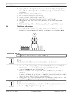
Notice!
To reset after a fire alarm, interrupt power to the receiver for a minimum of 1 sec. If the fire
panel does not allow you to reset, install a switch in series with Terminal 8.
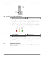
Wiring a remote indicator
A D306 Remote Indicator Plate is shipped with the D296 as a standard accessory. The D306
has three LEDs to indicate the detector’s condition and status and test points for measuring
the sensitivity voltage. Although the D306 is not required, the manufacturer recommends its
installation to check the detector’s condition from ground level. If using D306 Remote
Indicator Plate, install the remote indicator connector to the receiver as indicated in the
following figure.
5.2
Long-range Beam Smoke Detectors
Notices | en
15
Bosch Security Systems, Inc.
Installation Instructions
2014.01 | 06 | F.01U.068.899
Содержание D296 Series
Страница 1: ...Long range Beam Smoke Detectors D296 D297 en Installation Instructions ...
Страница 2: ......


