Installation
Compress 7001i AW – 6721835318 (2021/09)
14
CAN-BUS
NOTICE
The system will be damaged if the 12 V- and the CAN-BUS
connections are incorrectly connected!
The communication circuits are not designed for 12 V constant voltage.
▶ Check to ensure that the cables are connected to the contacts with
the corresponding markings on the modules.
The heat pump and indoor unit are connected by a communication line,
CAN-BUS.
A suitable cable for external cable installation
is wire LIYCY (TP)
2x2x0,75, or equivalent. An alternative cable should have a cross
section area of at least 0,75 mm
2
, and be a duplex cable, screened and
approved for outside use. The screen should only be earthed to the
chassis at one end (the indoor unit).
Maximum cable length is 30 m.
The connection is made with four wires, as the 12 V supply is also
connected. On the circuit board there is a marking for 12 V and CAN-BUS
connections.
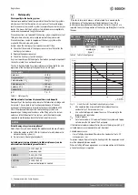
Switch Term
is used to indicate the start and end of a CAN-BUS loop.
The heat pump I/O module card should be terminated.
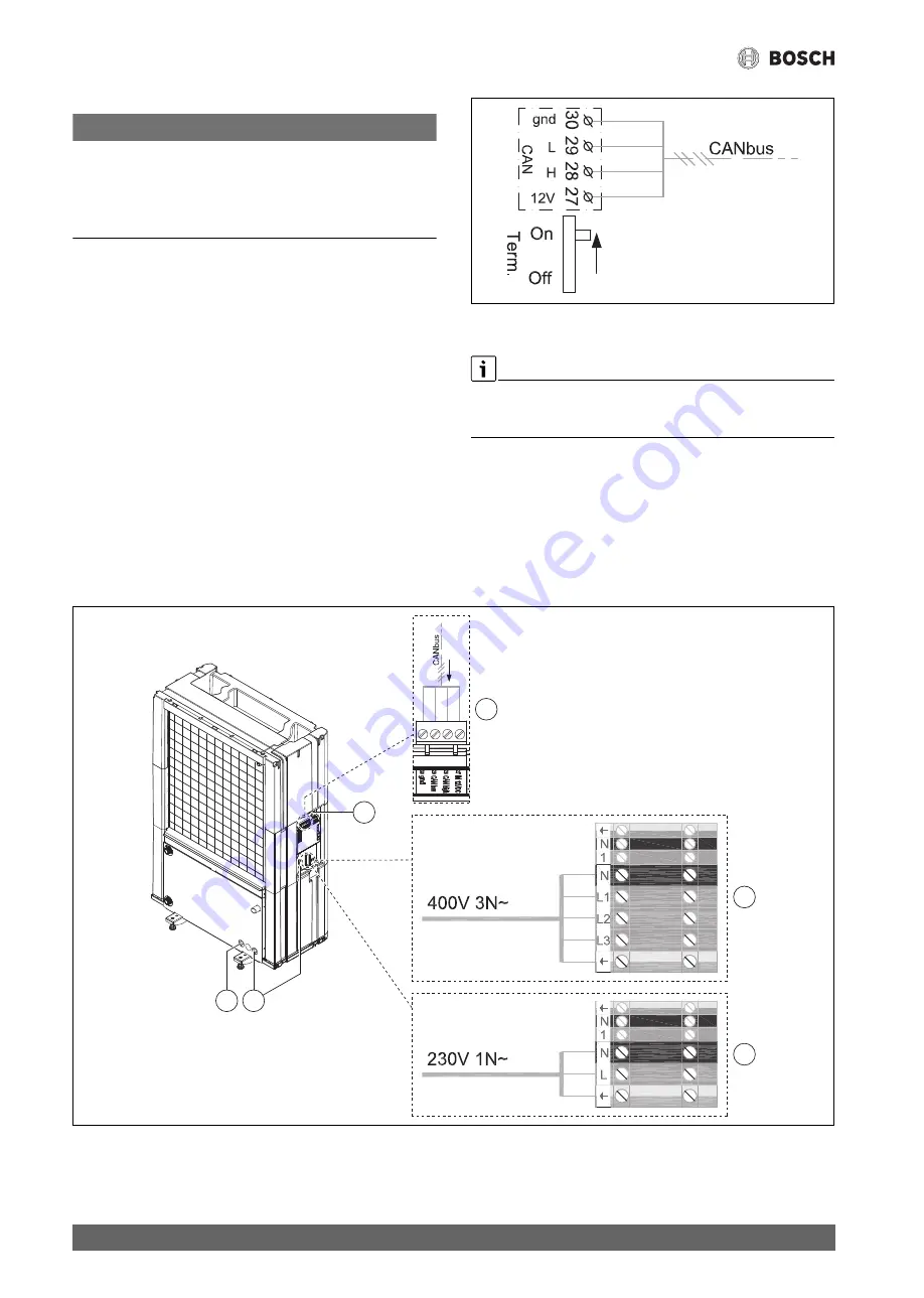
Fig. 19 Termination CAN-BUS
Connecting the heat pump
A CAN-BUS signal cable with the minimum dimensions 4 x 0.75 mm
2
and a maximum length of 30 m must be routed between the heat pump
and indoor unit.
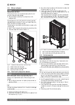
▶ Release belt (Velcro fastener).
▶ Remove the lock of the control device.
▶ Feed the connecting lead through the cable conduits. Use tension
springs if required.
▶ Connect cable as shown in the wiring diagram.
▶ Tighten all cable fixings if required.
▶ Reattach the cover of the control device.
▶ Reattach the belt.
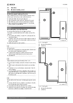
Fig. 20 Cable conduits and control device
[1]
Cable conduit, power supply
[2]
Cable conduit CAN-BUS
[A]
3-phase heat pump
[B]
1-phase heat pump
[C]
Connection CAN-BUS
1
2
2
A
C
B
Содержание Compress 7001i AW
Страница 1: ...6721835318 2021 09 GB Installation Manual Air to Water Heat Pump Compress 7001i AW 5 17 OR S T ...
Страница 30: ......
Страница 31: ......

