Bosch Combi FS Series Скачать руководство пользователя страница 90

Spare parts


Greenstar FS/Combi FS – 6 720 810 590 (2020/04)

90

19.5

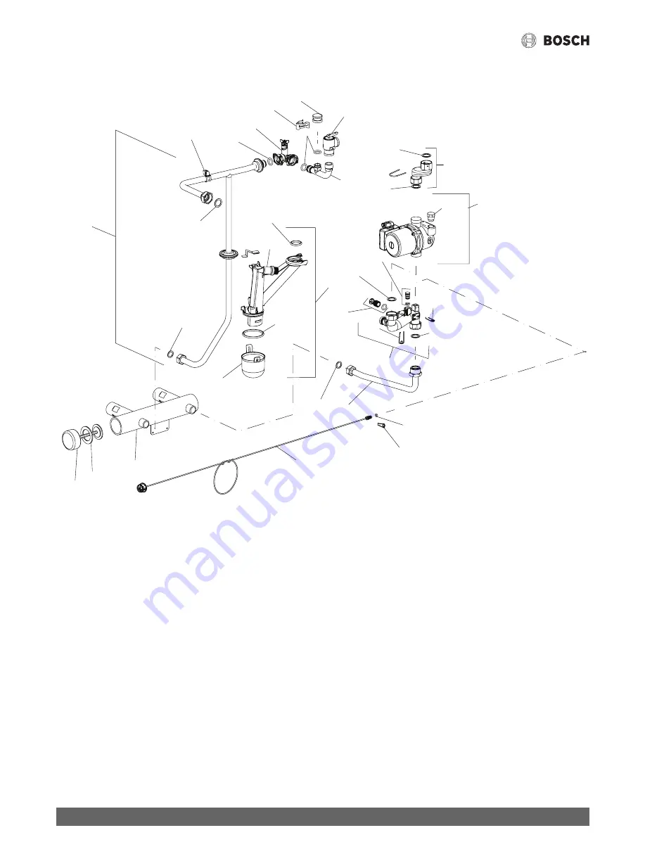
Group 5 Pipes Heat only boiler KBR...3A - Greenstar

Fig. 102 Group 5 Pipes heating boiler KBR.. 3A Greenstar

28

38

33

29

25

29

9

8

31

36

41

30

5

6

7

2

24

31 32

10

11

15

1

9

40

23

13

9

12

18

22

19

9

9

34

14

6720810590-77.2Wo

Содержание Combi FS Series

Страница 1: ...020 04 CA US Installation and Maintenance Instructions for Contractors Residential Gas Condensing Boiler Greenstar FS Combi FS 6720810590 00 2Wo KBR16 3A KBR21 3A KBR28 3A KBR35 3A KBR42 3A KWB28 3A KWB35 3A KWB42 3A ...

Страница 2: ...ntegrated expansion vessel KWB 3A boiler only 34 6 3 KBR 3A appliances heating boilers Selecting an expansion vessel 34 6 4 Selecting the installation location 34 6 5 Selecting the installation location 35 6 6 Low Loss Header LLH utilization 35 6 6 1 To utilize the LLH 35 6 7 Locating the appliance 36 6 7 1 Positioning the appliance 36 6 8 Installing a Low Water Cut off LWCO 36 6 9 Connecting the ...

Страница 3: ...king the mixer diaphragm 70 15 1 9 Expansion vessel 71 15 1 10 Setting the boiler water pressure 71 15 1 11 Testing system water quality 71 15 1 12 Checking the electrical wiring 71 15 2 Checklist for annual inspection and maintenance 72 16 Display 73 16 1 Readings on the display 73 17 Faults 74 17 1 Troubleshooting 74 17 2 Faults that are shown on the display 75 17 3 Faults that are not shown on ...

Страница 4: ...nfosymbolindicatesimportantinformationwherethereisnoriskto people or property Additional symbols Table 1 1 1 1 General safety instructions If you hear gas leaking Leave the building immediately Prevent others from entering the building Notify the police and fire department from outside the building From outside the building call the gas supply company and a trained and certified installer or servi...

Страница 5: ...d installer or service company DANGER Risk of personal injury or death from fire Do not use flammable or combustible material in the boiler room It is recommended not to store any items within 16 inches 415mm of the appliance CAUTION Appliance damage from contaminated combustion air Keep the combustion air free of corrosive substances e g halogenated hydrocarbons from painting operations or beauty...

Страница 6: ...r KWB 3A Contents of package 1 1 Gas condensing boiler 2 Set of documents 3 Adapter for connection of the LWCO 4 Gas conversion kit 5 Flue adapter2 6 Cardboard box of accessories 3 Information about the appliance KBR appliances are natural gas residential boilers for central heating and loading of an indirect fired DHW tank KWB appliances are natural gas residential combi boilers for central heati...

Страница 7: ...with test ports Variable speed fan Gas premix burner Heat exchanger temperature and high limit sensor LLH Supply temperature sensor Temperature limiter Safety relief valve pressure gauge Expansion vessel combi boiler only Connection possibility for DHW tank temperature sensor NTC heating boiler only Flue gas temperature limiter Connection for DHW DHW combi boiler only Internal motorized 3 way valv...

Страница 8: ... 4 101mm M9 8 3 16 207 3mm M10 3 7 16 86 7mm M11 6 13 16 173 3mm M12 4 5 8 117 6mm M13 11 3 16 283mm M14 5 1 8 131mm M15 28 1 16 713 5mm M16 31 788mm Ø 1 3 1 8 80mm Ø 2 4 15 16 125mm Table 3 M2 M1 M3 M4 M6 M8 M7 M9 M10 M11 M12 M14 M13 Ø1 Ø2 M15 M16 M5 6720810590 36 1Wo Symbol Description Connection size Domestic water inlet 3 4 19mm Domestic hot water outlet 3 4 19mm Heating return 11 4 31 8mm Hea...

Страница 9: ... 600mm 5 77 8 200mm 6 23 4 70mm 7 4 102mm 8 4 102mm 9 41 1042mm 10 183 8 467mm 11 199 16 497mm Zero clearance from combustibles permitted but 4 102mm recommended for serviceability 1 25mm distance to door if mounted inside a closet with 24 600mm in front of boiler for serviceability 12 300mm recommended distance behind the boiler for serviceability 6720810590 08 1Wo 1 2 3 6 4 5 7 8 9 10 11 ...

Страница 10: ...ombi FS 6 720 810 590 2020 04 10 3 7 Appliance layout heating boiler KBR 3A Fig 6 Appliance layout heating boiler KBR 18 19 20 21 22 23 25 5 6 7 9 10 12 13 14 15 17 16 11 3 1 24 32 31 30 29 28 27 35 36 37 38 39 33 34 4 6720810590 35 3Wo 26 41 40 2 ...

Страница 11: ...r maximum gas adjuster 13 Gas valve 14 Gas connection 15 Heating return connection 16 Heating supply connection 17 Low Loss Header with flow sensor 18 Fan 19 Electrode set 20 Primary heat sensor 21 Maximum safety sensor 22 Inspection and clean out cover 23 Condensate collector 24 Boiler circulator 25 Drain cock 26 Condensate trap 27 Heatronic boiler control 28 ON OFF switch 29 Burner on indicator ...

Страница 12: ... 720 810 590 2020 04 12 3 8 Appliance layout combi boiler KWB 3A Fig 7 Appliance layout combi boiler KWB 3A 22 23 24 25 26 27 30 28 31 7 8 9 10 11 12 14 15 17 18 19 21 20 16 13 3 4 5 1 29 38 37 36 35 34 33 41 42 43 44 45 39 40 6 6720810590 34 2Wo 32 47 46 2 ...

Страница 13: ...juster 15 Air vent 16 DHW thermostat 17 Gas valve 18 Gas connection 19 Central heat return connection 20 Central heating supply connection 21 Low Loss Header and flow sensor 22 Fan 23 Electrode set 24 Primary heat sensor 25 Maximum safety sensor 26 Inspection and clean out cover 27 Condensate collector 28 Flow meter 29 Pump 30 Three way valve 31 Drain cock 32 Condensate trap 33 Heatronic boiler co...

Страница 14: ...4 3 9 Electrical wiring heating boiler KBR 3A Fig 8 Electrical wiring diagram for heating boiler KBR 3A 6720810590 10 1Wo 1 T 2 5 4 3 6 LR LS N L NS 7 8 9 LP NP A F 1 2 4 B B 27 15 7 8 17 25 26 20 19 22 21 18 4 6 23 9 10 11 16 13 12 14 24 1 2 3 4 5 6 BUS TT out sen DHW sen LWCO ...

Страница 15: ...l heating pump 10 DHW tank primary pump or 3 way valve 11 120 VAC connection 12 Empty future connectivity 13 DHS Sen Domestic Hot Water temperature sensor NTC 14 LWCO Low Water Cut Off 15 Out Sen Outdoor temperature sensor 16 BUS BUS connection to programmer 17 Low voltage Installer connection box 18 Ignition electrode 19 Boiler block temperature limiter 20 Boiler circulator 21 Flame rod electrode...

Страница 16: ...16 3 10 Electrical wiring Combi boiler KWB 3A Fig 9 Electrical wiring diagram Combi boiler KWB 3A 14 13 1 2 3 4 5 6 BUS TT out sen DHW sen LWCO 15 6720810590 09 1Wo 1 2 5 4 3 6 LR LS N L NS 7 8 9 LP NP A F 1 2 4 B B 28 7 24 26 27 22 18 19 17 21 20 16 4 6 6 23 25 9 8 10 11 12 T ...

Страница 17: ...nal heating pump 10 120 VAC connection 11 Empty future connectivity 12 LWCO Low Water Cut Of 13 Out Sen Outdoor temperature sensor 14 BUS BUS connection to programmer 15 Low voltage Installer connection box 16 Ignition electrode 17 Boiler block temperature limiter 18 Flow meter turbine 19 3 way valve space heating DHW heating 20 Flame rod electrode 21 LLH Supply temperature sensor 22 Boiler circul...

Страница 18: ...r 3 5 10 5 8 7 26 1 LPG Propane in W C mbar 8 13 19 9 32 3 Flue gas Flue gas mass flow at maximum minimum nominal output gps 6 8 1 7 6 7 2 6 Flue gas temperature 176 140 F 80 60 C at max min nominal output F C 136 133 58 56 136 133 58 56 Flue gas temperature 104 86 F 40 30 C at max min nominal output F C 99 88 37 31 99 88 37 31 CO2 at maximum nominal output 9 4 11 0 CO2 at minimum nominal output 8...

Страница 19: ...r 3 5 10 5 8 7 26 1 LPG Propane in W C mbar 8 13 19 9 32 3 Flue gas Flue gas mass flow at maximum minimum nominal output gps 9 4 3 2 9 2 4 8 Flue gas temperature 176 140 F 80 60 C at max min nominal output F C 145 133 63 56 145 133 63 56 Flue gas temperature 104 86 F 40 30 C at max min nominal output F C 115 90 46 32 115 90 46 32 CO2 at maximum nominal output 9 4 11 0 CO2 at minimum nominal output...

Страница 20: ...r 3 5 10 5 8 7 26 1 LPG Propane in W C mbar 8 13 19 9 32 3 Flue gas Flue gas mass flow at maximum minimum nominal output gps 12 0 3 2 11 6 4 8 Flue gas temperature 176 140 F 80 60 C at max min nominal output F C 147 133 64 56 147 133 64 56 Flue gas temperature 104 86 F 40 30 C at max min nominal output F C 117 90 47 32 117 90 47 32 CO2 at maximum nominal output 9 4 11 0 CO2 at minimum nominal outp...

Страница 21: ... C mbar 3 5 10 5 8 7 26 1 LPG Propane in W C mbar 8 13 19 9 32 3 Flue gas Flue gas mass flow at maximum minimum nominal output gps 15 7 4 5 15 2 5 6 Flue gas temperature 176 140 F 80 60 C at max min nominal output F C 162 135 72 57 162 135 72 57 Flue gas temperature 104 86 F 40 30 C at max min nominal output F C 127 91 53 33 127 91 53 33 CO2 at maximum nominal output 9 4 11 0 CO2 at minimum nomina...

Страница 22: ...W 114 125 33 5 119 625 35 1 Max output rate 122 86 F 50 30 C BTU hr kW 114 125 33 3 119 625 35 1 Max output rate 176 140 F 80 60 C BTU hr kW 111 552 32 7 116 928 34 3 Gas connection value Natural gas Hs 1 010 BTU ft3 37 3MJ m3 ft3 hr m3 h 149 4 2 Liquid Propane Gas HD S 2 500 BTU ft3 37 3MJ m3 ft3 hr m3 h 59 1 7 Permissible gas inlet pressure NG in W C mbar 3 5 10 5 8 7 26 1 LPG Propane in W C mba...

Страница 23: ... 17 12 3 17 12 DHW Maximum DHW flow rate gpm litres min 2 64 10 2 64 10 Nominal DHW flow rate at 140 F 60 C outlet temperature gpm litres min 2 03 7 7 2 03 7 7 Outlet temperature F C 104 140 40 60 104 140 40 60 Maximum cold water inlet temperature F C 140 60 140 60 Maximum approved DHW pressure psi bar 150 10 3 150 10 3 Minimum water pressure psi bar 4 35 0 3 4 35 0 3 Flue gas Flue gas mass flow a...

Страница 24: ... litre 3 17 12 3 17 12 DHW Maximum DHW flow rate gpm litres min 3 17 12 3 17 12 Nominal DHW flow rate at 140 F 60 C outlet temperature gpm litres min 2 6 10 2 6 10 Outlet temperature F C 104 140 40 60 104 140 40 60 Maximum cold water inlet temperature F C 140 60 140 60 Maximum approved DHW pressure psi bar 150 10 3 150 10 3 Minimum water pressure psi bar 4 35 0 3 4 35 0 3 Flue gas Flue gas mass fl...

Страница 25: ...ax input rate 180 79 F 82 26 C BTU hr kW 125 828 36 9 129 021 37 8 Max output rate 104 86 F 40 20 C BTU hr kW 114 125 33 5 119 625 35 1 Max output rate 122 86 F 50 30 C BTU hr kW 114 125 33 3 119 625 35 1 Max output rate 176 140 F 80 60 C BTU hr kW 111 552 32 7 116 928 34 3 Output rate domestic hot water DHW 113 F 45 C BTU hr kW 114 125 33 5 129 750 37 9 Output rate domestic hot water DHW 140 F 60...

Страница 26: ...SI Z21 13 CSA4 9 latest edition for Gas Fired Low Pressure Steam and Hot Water Boilers Other confirmed approvals and certifications are indicated by labels on the boiler If so advised by the responsible agency the installation must satisfy the requirements of the standard for Controls and Safety Devices for Automatically Fired Boilers ANSI ASME CSD 1 Install CO detectors per local regulations Wall...

Страница 27: ...tor as required in accordance with the above provisions shall comply with NPA 720 and be ANSI UL 2034 listed and IAS certified SIGNAGE Ametalorplasticidentificationplateshallbepermanently mounted to the exterior of the building at a minimum height of eight 8 feet above grade directly inlinewiththeexhaustventterminal for the horizontally vented gas0fueled heating appliance or equipment The sign sha...

Страница 28: ... 16 Drain Bleed point 17 Combination fast fill back flow preventer 18 Expansion tank vessel 5 1 1 Utilizing the LLH Switch off and isolate the boiler Drain the boiler Remove front panel Locate the LLH at the left hand side of the lower section of the boiler 1 Unscrew the cap a from the body of the LLH c This will break the label across the cap and body indicating that the LLH has been employed 2 W...

Страница 29: ...pre wired link dry signal 2f Out Sen Outdoor sensor sold separately 2g LWCO pre wired link Low Water Cut Off switch sold separately 2h DHW Sen Tank sensor 2k Empty future connectivity 3 CZM100 Comfort Zone Manager 100 4 PZ1 System pump 5 VZ1 VZ2 Zone valves 6 24V Transformer 7 CRC100 or CRC200 Zone 1 Comfort room controller 8 CRC100 or CRC200 Zone 2 Comfort room controller 6720810590 72 2Wo 1 2 BU...

Страница 30: ...tion fast fill back flow preventer 17 Expansion tank vessel 5 2 1 To utilize the LLH Switch off and isolate the boiler Drain the boiler Remove front panel Locate the LLH at the left hand side of the lower section of the boiler 1 Unscrew the cap a from the body of the LLH c This will break the label across the cap and body indicating that the LLH has been employed 2 Withdraw the cap a and plunger a...

Страница 31: ... signal pre wired link dry signal 2f Out Sen Outdoor sensor sold separately 2g LWCO pre wired link Low Water Cut Off switch sold separately 2h DHW Sen Tank sensor 2k Empty future connectivity 3 CZM100 Comfort Zone Manager 100 4 PZ1 PZ2 Zone circulator pumps 5 CRC100 or CRC200 Zone 1 Comfort room controller 6 CRC100 or CRC200 Zone 2 Comfort room controller 1 2 BUS BUS 1 2 1 2 BUS BUS 1 2 24 V N L 1...

Страница 32: ...ppliance s electronics Additional accessories are required for this Connect the DHW circulation line at the cold water inlet as close as possible to the hydraulics connection plate Table 14 Recommended flow rates Youcandisplaytheflowratethroughtheheatexchangerwiththeservice function 6 d current flow through the turbine page 60 Open vented heating systems Convert open vented heating systems into cl...

Страница 33: ...e heating water causing corrosion damage All system leaks must be repaired Boiler sealer This boiler is not approved for use with boiler sealer LPG To protect the appliance against high pressure ANSI Z223 1 NFPA54 National fuel gas code or CAN CSA B 149 1 Natural Gas and Propane installation code Install a pressure regulator with a safety valve 6 1 1 Other important information The installation of...

Страница 34: ...all additional expansion vessel 6 3 KBR 3A appliances heating boilers Selecting an expansion vessel External expansion vessel Determine size of the expansion vessel Fig 18 Sample installation expansion vessel 6 4 Selecting the installation location Installation location requirements Follow the current national and local codes and regulations Follow country specific requirements Followinstallationi...

Страница 35: ...em is a single zone and has no additional circulators other than its integrated pump no modification of the LLH manifold is required If the heating system has additional circulators for example multiple zonesofpanelradiatororbaseboardheat thentheLLHplungermustbe removed to allow the hydraulic separation of the appliance from the system This allows the appliance to continue satisfying the demands o...

Страница 36: ...loor Ensurethefloorareaissuitableforinstallingaboilerandcantakethe wet weight of the appliance NOTICE Damaged caused by mechanical strain on the hydraulic and flue gas connections when adjusting the position of the appliance Do not apply any strain the connections when adjusting the boiler position Place boiler in its final location Release the locknuts on the boiler feet Adjust the boiler feet un...

Страница 37: ...ible into LWCO adapter located in the boiler accessory kit Follow the Hydrolevel Safgard 1100 instructions Fig 24 Installing a LWCO device LWCO adapter 1 Push the adapter with the LWCO onto the pipe 2 Secure with the clip Fig 25 Installing a LWCO device securing with a clip Connect the wires of the LWCO Section 7 1 9 The LWCO is positioned upright for technical reasons Tests have shown that all ai...

Страница 38: ...e screws provided Fig 26 Attaching the vent flange and gasket 1 Gasket 2 Vent flange 3 Screws Insert the flue gas adapter as far as it will go into the vent flange and align it Fig 27 Flue gas adapter 1 Combustion air test port 2 Flue gas test ports 3 Flue gas adapter 4 Vent flange Tighten the screws To avoid premature wear of the gaskets DO NOT use lubricants Using open venting Use a basket on th...

Страница 39: ...carbonmonoxideescaping into the boiler room Ensure that the flue pipes and seals are not damaged Use only sealing compounds primer and glue approved with the vent material Never install a barometricor a thermally controlled vent damper with this boiler Connect only one boiler to each flue system Do not route the flue system piping through or inside another duct that is used for exhausting air or o...

Страница 40: ... Ensure that condensate spilling from the termination does not create a hazard or a nuisance Vent termination must be 3 feet 915 mm above any forced air intake within 10 feet 3050 mm fig 31 1 YB Do not extend exposed vent pipe outside the building beyond recommended distance Condensate could freeze and block vent pipe Vent should terminate at least 3 feet 915 mm away from adjacent walls inside cor...

Страница 41: ...pe and fitting ANSI ASTM D1785 BH Gas venting systems ULC S636a Class IIA PVC Class IIB CPVC Class IIC Polypropylene certified to ULC S636 a Components of the certified vent systems must not be interchanged with other vent systems or unlisted pipe fittings Plastic components and specified primers and glues of the certified vent system must be from a single system manufacturer and not intermixed wi...

Страница 42: ...15mm Canada for models K 35 3A and K 42 3A X4 See note1 X6 7 feet 2135mm above public walkway YA At least 1 foot 305mm above grade or snow line YB Exhaust terminal must be at least 3 feet 915 mm above forced air inlet within 10 feet 3050 mm horizontally USA 6 feet 1830 mm above forced air inlet Canada Clearance in accordance with local installation codes and the requirements of the gas supplier in...

Страница 43: ... which can be subject to degradation from exhaust gases Ifmultipleboilersareinstalledinarow allowatleast1foot 305mm clearance between the vent termination of one and the combustion air intake of the other Fig 32 Horizontal venting system room air only Fig 33 Horizontal venting system room air only Key to fig 32 and fig 33 1 Intake 2 Exhaust Fig 34 Horizontal venting system sealed combustion Fig 35...

Страница 44: ...venting system room air only Fig 38 Vertical venting system sealed combustion Key to Fig 36 Fig 37 and Fig 38 1 Intake 2 Exhaust 3 Concentric termination X 12 305mm Y 12 305mm above maximum snow level or at least 24 610mm whichever is greater 6 720 810 590 23 1W Y 1 2 6 720 810 590 24 1Wo 1 Y X 2 6 720 810 590 25 1Wo 1 2 Y X ...

Страница 45: ...er is greater The transitions from rigid to corrugated pipe must conform to the S636 standard Plastic vent pipe for gas fired appliances Fig 40 PolyPro Flex Chimney Cap PP vertical venting system sealed combustion 1 Intake 2 Exhaust Fig 41 Horizontal venting system telescopic concentric vent kit 2 6 720 810 590 26 1Wo Y X 1 Y X X 6 720 806 922 08 2O 1 2 5 8 per foot 52 mm per metre 6 720 810 590 2...

Страница 46: ... for fittings Example Model KBR 28 3A 90 elbow used 2 45 elbow used 2 Maximum straight vent pipe allowed 38ft 11 6m Installations Fig 32 33 34 36 37and 39 Separate terminations 2 PIPE Maximum effective vent pipe length allowed for Ø 2 pipe KBR 16 3 KBR 35 3 KBR 21 3 KWB 35 3 Number of 90 KBR 28 3 KBR 42 3 elbows used KWB 28 3 KWB 42 3 1 81ft 24 6m 65ft 19 8m 2 76ft 23 1m 57ft 17 3m 3 71ft 21 6m 48...

Страница 47: ... applicable local codes and regulations Theboilermustbeproperlyelectricallygroundedinaccordancewiththe requirements of the authority having jurisdiction or in the absence of such requirements with the National Electrical Code ANSI NFPA 70 and or the Canadian Electrical Code Part I CSA C221 1 Electrical Code Provide a dedicated circuit breaker for the boiler and heating system rated at least 15A Al...

Страница 48: ... external pump 1 L 120VAC 60Hz 2 PE GND ground 3 N Neutral 4 Black plug in the junction box upon delivery Connect black plugs and insert grommet until stop Fig 48 Cable connected external pump Refer to Use Service function 5 E to set connection to 01 DHW recirculation pump or Use Service function 5 E to set connection to 02 external heating zone pump in an unmixed heating circuit or Use Service fu...

Страница 49: ...il stop Fig 52 Cable connected mains power supply Mount junction box on the rail 7 1 7 Low voltage LV junction box The low voltage installer junction box provides connections to sensors thermostat and programmers Bosch room controls Connect only Bosch room controls to the internal BUS of this boiler For installation and electrical connection of Bosch controls see installation instructions for the ...

Страница 50: ...w be wired to the Lowvoltage LV connection DHW Sen position 5 Fig 55 DHW tank sensor connector plug removal 7 1 9 Connecting the LWCO device Install a 24VAC 20VA transformer near the boiler Follow LWCO manufacturer s instructions Connect the lead labelled BOILER GROUND green to pin 2 center Fig 51 2 of the white plug in the boiler junction box Connecttheleadslabelled24VHOT red and24VCOMMON white t...

Страница 51: ...ad of the heating system page 34 Manually open radiator and or zone valves as applicable Open heating supply and return valves fill heating system to 14 5 to 21 75 psi 1 1 5 bar and close fill valve Bleed all air from the system Iftheboilerwaterpressurehasdropped filltheheatingsystemagain to 14 5 to 21 75 psi 1 to 1 5 bar On KBR 3A appliances heating boilers with a DHW tank open the cold water sup...

Страница 52: ...y The instructions contain information on setting up the operating mode adjusting the room temperature heating economically for comfortable temperatures mounting the controller in the reference room Fig 60 FW 200 controls Table 27 BodyText 8 5 After commissioning Check flue path for tightness Check gas supply dynamic pressure Fig 12 3 Check that condensate is being discharged from the condensate h...

Страница 53: ... 7 KWB 3A appliances combi boilers Setting the DHW temperature Set the DHW temperature on the DHW thermostat The set DHW temperature flashes on the display for 30 seconds Fig 62 Set the DHW temperature combi boiler KWB 3A Table 29 Typical DHW temperatures for combi boiler KWB 3A ECO button Pressing and holding the ECO button until it lights up switches between Comfort mode and Economy mode Comfort...

Страница 54: ...e display Fig 66 Key pad lock Unlocking the key pad Press the key pad lock button until the display shows only the supply temperature 9 KBR 3A appliances with DHW tank Thermal disinfection Thermal disinfection covers the DHW system including the taps For solar DHW tanks the solar portion of the tank is not covered WARNING Risk of scalding Hot water can result in severe scalding Carry out thermal d...

Страница 55: ...boiler KWB 3A Key to figures 68 and 69 1 Residual head pressure at speed 1 2 Residual head pressure at speed 2 3 Residual head pressure at speed 3 default setting 4 Head pressure of the boiler pump by itself at speed 3 H Head pressure in feet of head m V Circulating water volume in gallons per minute l h In order to save as much energy as possible and keep any water circulationnoisestoa minimum se...

Страница 56: ... until it illuminates The display shows a code such as 1 A first service level Press the ECO button and key pad lock button simultaneously until the code 8 A appears second service level Onthesecondservicelevel selecttheservicefunction8 Eandvalue 00 The appliance restarts with the default settings 11 2 Overview of service functions 11 2 1 First service level Press and hold the service button until...

Страница 57: ...en there is a demand for heat the central heating pump and the burner start up Pump control mode 02 Do not use Pumpcontrolmode03 Thecentralheatingpumprunscontinuously exceptions See heating control operating instructions Pump control mode Intelligent control of central heating pump in heating systems with weather compensation control The heating zone pump is only switched on when needed Default se...

Страница 58: ...is aborted or has been active for 15 minutes the appliance reverts to default mode 02 The appliance runs for 15 minutes at maximum output The display shows 2 F When this service function is aborted or has been active for 15 minutes the appliance reverts to default mode Default setting is 00 Service function 3 A Automatic anti cycle function If a outdoor reset control is connected there is no need ...

Страница 59: ...activated with the service function 4 d 00 Warning tone off 01 Warning tone on Default setting is 01 ON Service function 4 E Appliance type This service function displays the appliance type detected Possible displays are 00 Central heating only 01 Combi appliance 02 DHW tank temperature sensor NTC connected to Heatronic 03 DHW tank thermostat connected to Heatronic 04 Stratified DHW tank 05 Tank w...

Страница 60: ...illuminated and faults flashing The following settings are possible 00 Off 01 On burner operation and flashing fault present Default setting is 00 Service function 7 b 3 way valve in center position After the value 01 has been saved the 3 way valve moves to the center position This allows draining the system completely and removing the motor easily When you exit this service function the appliance...

Страница 61: ...n transformer damage Never leave this function on for longer than 2 minutes at a time This function enables permanent ignition without gas supply to test the performance of all ignition related components The following settings are available 00 Off 01 On Default setting is 00 Service function 9 A Constant mode Thisfunctionsetsoneoperatingmodepermanently Servicefunction 2 F Operating mode page 55 T...

Страница 62: ...ofcarbonmonoxidemayresultinpropertydamage personal injury or loss of life Before carrying out electrical work disconnect the installation from the power supply at the emergency shutoff switch or by disengaging the heating system circuit breaker Take measures to prevent accidental reconnection The installer is responsible for the proper conversion of this appliance The conversion is not complete un...

Страница 63: ...itude adjustment which compensatesfortheeffectsofthinair andarethereforeNOTderatedup to 6000 feet 1829 m Above 6000 feet 1829 m a rate of 3 per 1000 feet 305 m applies TheBoschGreenstarboilerisfactorysetforinstallationbelow2000feet 610 m above sea level Correction of the fan speed curve of the burner Useservicefunction0 dtoadjusttheelevationsetting page 60 12 2 Setting the gas air ratio CO2 or O2 ...

Страница 64: ...settings at maximum and minimum nominal output and readjust if necessary RepeatedlypresstheemissionstestbuttonCuntilthelightgoesout The display returns to the supply temperature Record the CO2 or O2 levels and the CO content of the flue gas in the commissioning log Reinstallthescrew Fig 78 3 tocoverthegasvalveadjustment screw Removefluegasprobeandrefittheplugintothefluegastestportand tighten to se...

Страница 65: ...imum nominal output Minimum nominal output You have 15 minutes to complete the tests After that the appliance returns to default mode 13 2 Measuring CO content of the flue gas Use a multiport flue gas probe for the measurements Open one of the flue gas test ports Fig 75 Insert the flue gas probe approx 2 inches 70 mm into the test port and seal around it Press the emissions test button to select m...

Страница 66: ...on the gas train DANGER Risk of flue gas poisoning Check for leaks after carrying out work on the venting system DANGER Risk of electric shock Always disconnect the appliance from the mains power before performing any work Always disconnect the appliance from the mains power before performing any work Take measures to prevent accidental reconnection NOTICE Insufficient antifreeze can accelerate co...

Страница 67: ... remove pipe connections Fig 83 Removing pipe connections Remove the boiler pressure gauge from the Heatronic boiler control Fig 84 Removing the boiler pressure gauge Loosen the quick releases steps 1 and 2 and remove the hydraulic assembly in its entirety step 3 Fig 85 Removing the hydraulic assembly 6720810590 41 1Wo 6720810590 42 1Wo 6720810590 32 1Wo 1 3 2 6720810590 43 1Wo 1 ...

Страница 68: ... clean or replace as required Re install electrode set with new gaskets and check for leaks Fig 87 Reinstalling the electrode set Fig 88 Check for gas leaks 15 1 5 Burner servicing DANGER Fire Improper operation of the burner Only operate the burner while installed in a boiler Remove the burner cover steps 1 4 Fig 89 Removing the burner cover Remove the burner and clean the components Fig 90 Burne...

Страница 69: ...er through visual inspection If mechanical cleaning is required For cleaning the heat exchanger use Bosch main heat exchanger gaskets the heat exchanger brush and the heat exchanger cleaning blade which are available as spare parts Remove the condensate trap steps 1 and 2 and place a suitable container underneath Fig 91 Removing the condensate trap With the cleaning blade clean the heat exchanger ...

Страница 70: ... 1 ft lbs 5 5 Nm and 5 1 ft lbs 7 0 Nm 15 1 7 Cleaning condensate trap Remove condensate trap steps 1 and 2 and check heat exchanger orifice for clear passage Fig 96 Removing the condensate trap Remove and clean the condensate trap lid Check condensate hose and clean if necessary Fill the condensate trap with approx 1 cup 1 4 l of water and reinstall it 15 1 8 Checking the mixer diaphragm Open the...

Страница 71: ...r being introduced into the system If the pressure is not held check the expansion vessel and heating system for leaks 15 1 11 Testing system water quality Take a representative sample of the system water and analyze pH using a pH meter or pH test strips Table 36 Waterpreparationforfillingandmaintainingtheheatingsystem pH value If the value is outside of the permitted range drain the system flush ...

Страница 72: ...ent pipes 4 Dynamic gas pressure Section 12 3 inches W C mbar 5 Gas air ratio at min max nominal output table 77 min max 6 Gas and water side leak test Section 6 10 7 Inspect electrodes Section 15 1 4 8 Inspect heat exchanger block Section 15 1 6 9 Check burner Section 15 1 5 10 Inspect diaphragm in mixer unit Section 15 1 8 11 Clean condensate trap Section 15 1 7 12 With the system depressurized ...

Страница 73: ...ing the button and holding longer than 3 seconds Save function The display shows the supply temperature in alternation with The appliance works for 15 minutes at the minimum nominal output service function 2 F The display shows the supply temperature in alternationwith Theapplianceworkswiththeset maximum output in heating mode service function 1 A The display shows the supply temperature alternati...

Страница 74: ...f this is not possible protect your heating system from freezing by draining the heating system and hot water pipes at the lowest point NOTICE The Heatronic boiler control can be damaged by leaking water Cover the Heatronic prior to work on water filled components TheHeatronicboilercontrolmonitorsallsafetyandcontrolcomponents If a fault arises during operation an audible warning tone sounds Press ...

Страница 75: ...ature limiter locked out Check temperature sensor and leads for interruptions or shorts and replace if defective Temperature guard TB1 has tripped Check if jumper across 8 9 or PR P0 is missing Reset external temperature limiter if installed Reset LWCO if installed d5 External supply temperature sensor defective low loss header The external supply temperature sensor was recognized on the BUS and t...

Страница 76: ...ll restart Check electrical plug in contacts and ignition leads replace PCB if defective Check gas air ratio correct if out of specification F1 Internal data error Reset boiler to the factory default setting service function 8 E F7 Flame detected even when burner is off Check electrodes replace if defective Check flue gas system clean or repair if defective Check PCB for moisture dry if needed FA ...

Страница 77: ...sure adjust if defective Check power supply Check electrodes for visual damage replace if defective Check flue gas system clean or repair if defective Check gas air ratio replace gas valve if defective Check gas valve replace if defective Check burner replace if required DHW has unpleasant odor or has a dark color Perform thermal disinfection of the DHW circuit Replace sacrificial anode in the tan...

Страница 78: ...sistance 32 0 33 555 50 10 21 232 68 20 13 779 86 30 9 128 104 40 6 205 122 50 4 298 140 60 3 025 158 70 2 176 176 80 1 589 194 90 1 177 212 100 886 Temperature F C Testing tolerance 10 Resistance 68 20 14 772 77 25 11 981 86 30 9 786 95 35 8 047 104 40 6 653 113 45 5 523 122 50 4 608 131 55 3 856 140 60 3 243 149 65 2 744 158 70 2 332 167 75 1 990 176 80 1 704 185 85 1 464 194 90 1 262 203 95 1 0...

Страница 79: ... nominal output Notes regarding under or overpressure operation Gas setting and flue gas test Set gas type Inlet gas pressure W C mbar Gas static supply pressure W C mbar Selected maximum output MBH kW Selected minimum output MBH kW Gas flow rate at maximum nominal output gpm l min Gas flow rate at minimum nominal output gpm l min Net calorific value HiB per gas supplier MBTU ft3 kWh m3 CO2 at max...

Страница 80: ...unction check carried out Leak test carried out on the gas and water sides Commissioningincludeschecking thesettings avisualheating leak test and afunctional checkof the boiler and control Thesysteminstallerconducts a test of the heating system The system named above has been checked to the extent described ___________________________________________________________ Name of service engineer The do...

Страница 81: ...8 3 KBR35 3 KBR42 3 KWB28 3 KWB35 3 KWB42 3 Spare parts list Group 1 Sheet metal Section 19 1 Group 2 Burner Heat exchanger Section 19 2 Group 3 Gas valve Section 19 3 Group 4 Pipes Combi boiler KWB 3A Section 19 4 Group 5 Pipes Heat only boiler KBR 3A Section 19 5 Group 6 Control box Section 19 6 Group 7 Hydraulic block Combi boiler KWB 3A Section 19 7 Group 8 Accessories for service installation...

Страница 82: ...Spare parts Greenstar FS Combi FS 6 720 810 590 2020 04 82 19 1 Group 1 Sheet metal Greenstar Fig 98 Sheet metal Greenstar 6720810590 73 1Wo ...

Страница 83: ...5 8 716 117 335 10 Expansion vessel 8 715 407 328 0 11 Shape screw 8 713 407 021 0 12 Washer 80mm 8 711 004 232 0 13 Resonator 8 716 117 337 14 Adaptor 8 716 117 334 16 Silencer 8 710 725 353 0 17 Seal 8 711 004 278 0 18 Throttle disc 8 7 10 100 209 0 19 Screw M5 x 20mm 8 716 117 397 20 Seal 8 716 117 487 21 Damper 2x 8 713 204 016 0 22 Assembly junction box cover 8 716 117 488 24 Screw 10x 2 910 ...

Страница 84: ...FS Combi FS 6 720 810 590 2020 04 84 19 2 Group 2 Burner Heat exchanger Greenstar Fig 99 Group 2 Burner Heat exchanger Greenstar 21 20 19 31 15 16 14 12 8 11 5 9 36 10 23 3 2 4 3 6 7 1 9 16 19 4 24 33 33 17 6720810590 74 4Wo ...

Страница 85: ...8 0 6 Sensor NTC Control stat 8 716 117 332 7 Bracket NTC 8 716 117 331 8 Cover 8 711 000 262 0 9 Sealing 8 710 103 153 0 10 Shield 8 718 003 836 0 11 Clip 10x 8 710 100 190 0 12 Set of electrodes 8 718 664 3010 14 Seal 8 718 664 402 15 Burner 8 718 006 658 0 16 Burner sealing 8 711 004 168 0 17 Cover 8 715 406 318 0 17 Cover 8 715 416 029 0 18 Fixing set 8 710 305 296 0 19 Seal 8 711 004 146 0 20...

Страница 86: ...Spare parts Greenstar FS Combi FS 6 720 810 590 2020 04 86 19 3 Group 3 Gas valve Fan Mixing chamber Greenstar Fig 100 Group 3 Gas valve Fan Mixing chamber Greenstar 6720810590 75 1Wo ...

Страница 87: ...r set mounting set 8 716 115 535 0 10 Pressure balance tube 8 718 221 063 0 11 Gas pipe top USA 8 718 225 762 0 13 Gas pipe 8 710 735 387 0 14 Plastic Seal 8 716 117 348 16 Washer 8 729 000 183 0 17 Fan RG128 USA 8 718 226 184 0 18 O ring 10x 8 722 880 175 0 19 Screw M4 x 8mm taptite zc pl p h 2 914 411 412 0 20 Air limiter 8 710 505 210 0 20 Air limiter 8 710 505 212 0 20 Air limiter 8 716 117 45...

Страница 88: ...pare parts Greenstar FS Combi FS 6 720 810 590 2020 04 88 19 4 Group 4 Pipes combi boiler KWB 3A Greenstar Fig 101 Group 4 Pipes combi boiler KWB 3A Greenstar Item 39 Flow sensor not shown 0010025824 01 ...

Страница 89: ... 20 Pipe CH flow 8 716 117 519 21 Elbow flow pipe 8 718 688 953 0 22 Pressure gauge USA 8 716 117 503 23 O ring 2 62 x 6 02 ID EPDM 10x 8 716 140 810 0 24 Upper rear pipe 8 716 119 511 25 O ring 26 34 x 5 33 5x 8 710 205 098 0 26 Washer set 8 710 103 154 0 27 O ring 13 87 x 3 5 L 10x 8 716 107 439 0 28 Cap closing connection 8 716 117 508 29 Temperature sensor 8 716 119 512 30 Assembly LLH 8 716 1...

Страница 90: ... 810 590 2020 04 90 19 5 Group 5 Pipes Heat only boiler KBR 3A Greenstar Fig 102 Group 5 Pipes heating boiler KBR 3A Greenstar 28 38 33 29 25 29 9 8 31 36 41 30 5 6 7 2 24 31 32 10 11 15 1 9 40 23 13 9 12 18 22 19 9 9 34 14 6720810590 77 2Wo ...

Страница 91: ...8 718 226 180 0 15 Expansion vessel plug 8 716 117 898 18 Pump KBR USA 8 718 226 172 0 19 Return pipe 8 710 735 450 0 22 Plug 8 713 301 152 0 23 O ring 26 34 x 5 33 5x 8 710 205 098 0 24 Washer set 8 710 103 154 0 25 Temperature sensor 8 714 500 117 0 28 Cap closing connection 8 716 117 508 29 O ring 17 x 4 5x 8 710 205 085 0 30 Assembly LLH 8 716 117 509 31 Washer 23 9 x 17 2 x 1 5 1x 8 716 115 6...

Страница 92: ...Spare parts Greenstar FS Combi FS 6 720 810 590 2020 04 92 19 6 Group 6 Control box Greenstar Fig 103 Group 6 Control box Greenstar 6720810590 78 1Wo ...

Страница 93: ...14 432 509 0 Code plug 2520 NG 23 8 714 432 520 0 Code plug 2521 LPG 31 8 714 432 521 0 Code plug 2524 NG 23 8 714 432 524 0 Code plug 2525 LPG 31 8 714 432 525 0 Code plug 2528 NG 23 8 714 432 528 0 Code plug 2529 LPG 31 8 714 432 529 0 11 Cover 8 737 702 329 0 12 Grommet 10x 8 710 506 185 0 16 Earth harness 8 716 117 523 17 Harness low voltage appliance 8 716 117 524 20 Fuse 8 744 503 045 0 21 H...

Страница 94: ...Spare parts Greenstar FS Combi FS 6 720 810 590 2020 04 94 19 7 Group 7 Hydraulic block Combi boiler KWB 3A Greenstar Fig 104 Group 7 Hydraulic block combi boiler KWB 3A Greenstar 6720810590 79 2Wo ...

Страница 95: ...0x 8 716 771 353 0 22 Air vent valve 8 716 106 445 0 23 Return unit 8 716 106 844 0 24 Safety clip supply sensor 8 716 106 488 0 25 Pressure relief valve DHW 8 717 401 029 0 26 O ring 6 00 x 2 50 WRAS KTW 1x 8 716 116 074 0 27 Drain valve 8 716 771 432 0 28 Expansion vessel plug 8 716 117 507 29 O ring 13 87 x 3 53 L 10x 8 716 107 439 0 30 Safety clip inlet adapter 8 716 106 432 0 31 Diverter valv...

Страница 96: ...tion Greenstar Table 55 Group 8 Accessories for service installation Greenstar Item Designation KBR16 3 KBR21 3 KBR28 3 KBR35 3 KBR42 3 KWB28 3 KWB35 3 KWB42 3 Order number Brush set WB5 7 719 002 502 Cleaning blade WB5 7 719 002 503 Packaging 7 716 117 537 Adapter minimum pressure switch 8 718 226 386 0 ...

Страница 97: ......

Страница 98: ......

Страница 99: ......

Страница 100: ...552 1100 Fax 603 965 7581 www bosch climate us U S A Products manufactured by Bosch Thermotechnik GmbH Junkersstrasse 20 24 D 73249 Wernau www bosch thermotechnology com Bosch Thermotechnology Corp reserves the right to make changes without notice due to continuing engineering and technological advances ...

Отзывы: