


Installation
5
Climate Class 6100i/8100i – 6721831491 (2020/11)
▶ Fasten the mounting plate with a further six screws and wall plugs so
that the the mounting plate lies flat on the wall.
▶ Drill wall outlet for the piping (wall outlet should be behind the indoor
unit as a recommendation
Fig. 5).
The markings [1] serves the positioning of the hole.
▶ Change the position of the condensate pipe if necessary (
Fig. 6).
The pipe fittings on the indoor unit are generally located behind the
indoor unit. We recommend extending the pipes before mounting the
indoor unit.
▶ Establish pipe connections as described in Chapter 3.4.
▶ Bend the piping in the required direction if necessary, and knock out
an opening on the side or underneath on the cover panel (
Fig. 8).
▶ Route the piping through the wall and attach the indoor unit to the
mounting plate (
Fig. 9).
▶ Additional mirror metal sheets are available for the coloured models
CLC8101i... T/S/R, and must be attached at the designated points
(
– Determine the position of the mirror metal sheets.
1)
– Pull off adhesive foil.
– Match mirror metal sheets to the mirrored metal sheets that are
already installed [1].
If it is necessary to take the indoor unit off the mounting plate:
▶ Press against the marks on the bottom of the indoor unit, and pull the
indoor unit towards the front (
These marks are not visible on the coloured product types CLC8101i...
T/S/R as a mirror metal sheet is attached at this point. The indoor unit
can still be removed from the wall in this manner by pressing at the
corresponding points.
3.3.2
Installing the outdoor unit
▶ Place the box so it is facing upwards.
▶ Cut and remove the packing straps.
▶ Pull the box up and off and remove the packaging.
▶ Prepare and install a floor or wall mounting bracket, depending on the
type of installation.
▶ Mount or hang the outdoor unit using the anti-vibration coupling for
the feet which is supplied with the unit or is provided on site.
▶ Ensure for the condensate pipe on site.
▶ Remove the cover for the pipe connections (
Fig. 12).
▶ Establish pipe connections as described in Chapter 3.4.
▶ Mount the cover for the pipe connections again.
3.4
Pipework connection
3.4.1
Connecting refrigerant lines to the indoor and outdoor unit
CAUTION
Discharge of refrigerant due to leaky connections
Refrigerant may be discharged if pipe connections are incorrectly
installed.
▶ When reusing flared joints, always fabricate the flared part again.
Copper pipes are available in metric and imperial sizes, the flare nut
thread is however the same. The flared fittings on the indoor and outdoor
unit are intended for imperial sizes.
▶ When using metric copper pipes, replace the flare nuts with nuts of a
suitable diameter (
Tab. 6).
▶ Determine pipe diameter and length (
Page 3).
▶ Cut the pipe to length using a pipe cutter (
Fig. 7).
▶ Deburr the inside of the pipe at both ends and tap to remove swarf.
▶ Insert the nut onto the pipe.
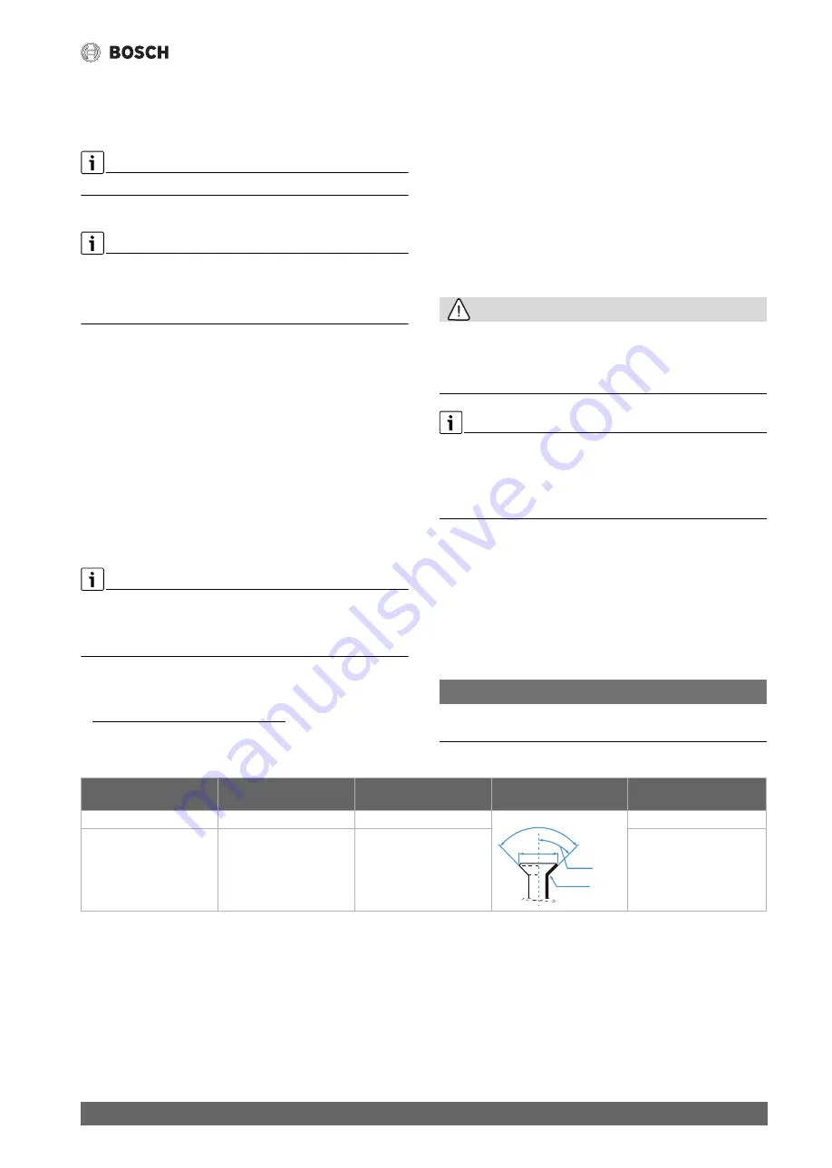
▶ Widen the pipe using a flaring tool to the size indicated in the tab. 6.
It must be possible to slide the nut up to the edge but not beyond it.
▶ Connect the pipe and tighten the screw fitting to the torque specified
in the tab. 6.
▶ Repeat the above steps for the second pipe.
NOTICE
Reduced efficiency due to heat transfer between refrigerant pipes
▶ Thermally insulate the refrigerant lines separately.
▶ Fit the insulation on the pipes and secure.
Table 6 Key data of pipe connections
3.4.2
Connect condensate pipe to the indoor unit
The condensation catch pan of the indoor unit has two connections. A
condensate hose and bung are mounted on these connections at the
factory and can be replaced (
Fig. 6).
▶ Only route the condensate hose with a slope.
1) Depending on the position of the pipes, either all 4 or only 3 mirror metal sheets
are required.
External diameter of
pipe Ø [mm]
Tightening torque [Nm]
Flared opening diameter
(A) [mm]
Flared pipe end
Pre-assembled flare nut
thread
6.35 (1/4")
18-20
8.4-8.7
1/4"
9.53 (3/8")
32-39
13.2-13.5
3/8"
R0.4~0.8
A
45°± 2
90°± 4


