background image

2 6  |


Bosch Climate 5000 Series Ducted Type (Medium & High Static) Air Conditioner / Heat Pump


Installation Manual

05.2019 

|

 Bosch Thermotechnology Corp.

Data subject to change

4. 

Clamp down the cable with the cable clamp.

5. 

Insulate unused wires with electrical tape. Keep them away from any 
electrical or metal parts.

6. 

Reinstall the cover of the electric control box.

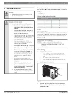
Indoor Unit wiring

1. 

Prepare the cable for connection:

a.  Using wire strippers, strip the rubber jacket from both ends of the 

signal cable to reveal about 15cm (5.9”) of the wire.

b.  Strip the insulation from the ends of the wires.

c.  Using a wire crimper, crimp the u-lugs to the ends of the wires.

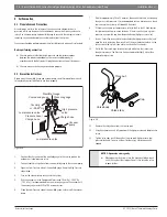
2. 

Remove the cover of the electric control box on your indoor unit. 

3. 

Connect the u-lugs to the terminals. Match the wire colors/labels with 
the labels on the terminal block. Firmly screw the u-lug of each wire to its 
corresponding terminal. Refer to the Serial Number and Wiring Diagram 
located on the cover of the electric control box.

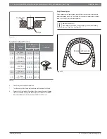
Figure 54

Connective wiring diagram

Wiring diagram

Control box

Magnetic ring (if supplied and packed with the accessories)

Figure 55

1   2   3   

 Pass the belt through
 the hole of the Magnetic 
ring  to fix it on the cable  


 CAUTION: 


While connecting the wires, please strictly follow the 
wiring diagram.


The refrigerant circuit can become very hot. Keep the 
interconnection cable away from the copper tube.

4. 

Clamp down the cable with the cable clamp. The cable must not be loose or 
pull on the u-lugs.

5. 

Reattach the electric box cover.


   If a quick-connect cable is attached to the indoor unit's terminal block,

remove this cable and discard. This quick-connect cable is used in the 
manufacturer production testing process.

Содержание BMS500-AAM018-1CSXRA

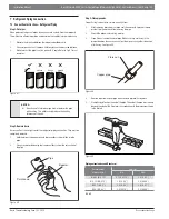
Страница 1: ...Bosch Ducted Type Medium High Static Air Conditioner Heat Pump Climate 5000 Series Installation Manual ...

Страница 2: ...2 Bosch Climate 5000 Series Ducted Type Medium High Static Air Conditioner Heat Pump Installation Manual 05 2019 Bosch Thermotechnology Corp Data subject to change ...

Страница 3: ...K Models Medium Static 8 4 2 60K Model High Static 9 5 Indoor Unit Installation 10 6 Outoor Unit Installation 20 7 Refrigerant Piping Connection 23 7 1 Connection Instructions Refrigerant Piping 23 8 Connecting Signal Power Cable 25 8 Air Evacuation 28 8 1 Preparations and Precautions 28 8 2 Evacuation Instructions 28 8 3 Adding Refrigerant 29 9 Electrical and Gas Leak Checks 30 9 1 Electrical Saf...

Страница 4: ...ARNING ELECTRICAL HAZARD Do not modify the length of the power supply cord or use an extension cord to power the unit Do not share the electrical outlet with other appliances Improper or insufficient power supply can cause fire or electrical shock WARNING INSTALLATION REQUIREMENTS Installation must be performed by a licensed contractor and per the instructions in the installation manual Improper i...

Страница 5: ...be replaced by the manufacturer its service agent or similarly qualified persons such as a licensed electrician in order to avoid a hazard The product must be properly grounded at the time of installation or electrical shock may occur CAUTION BURN HAZARD For units that have an auxiliary electric heater do not install the unit within 1 meter 3 feet of any combustible materials Do not install the un...

Страница 6: ...parts and components to install the air conditioner Improper installation may result in water leakage electrical shock and fire or cause the equipment to fail Name Image Quanity Soundproof insulation sheath 2 Drain joint 1 Seal ring 1 Copper nut 60k model only 2 Display control unit 1 Magnetic ring for S1 S2 wire 36k 48k models only 1 Magnetic ring for connective cable 1 Magnetic ring for wired con...

Страница 7: ...logy Corp 05 2019 Data subject to change 3 Installation Summary Figure 1 L N 1 2 3 4 5 MC MC 6 7 Install the indoor unit Page 10 Install the outdoor unit Page 20 Install the drainpipe Page 16 Evacuate the refrigeration system Page 28 Connect the wires Page 25 Connect the refrigerant pipes Page 23 Perform a test run Page 31 ...

Страница 8: ...ta subject to change 4 System Components 4 1 9K 48K Models Medium Static Figure 2 Air outlet Air inlet Air filter Drain hose Electric control cabinet Refrigerant connecting pipe Screw Air filter Illustrations in this manual are for explanatory purposes The actual shape of your indoor unit may be slightly different The actual shape shall prevail ...

Страница 9: ...orp 05 2019 Data subject to change 4 2 60K Model High Static Figure 3 Air outlet Air inlet Drain hose Refrigerant connecting pipe Electric control cabinet Air filter Heat exchanger Illustrations in this manual are for explanatory purposes The actual shape of your indoor unit may be slightly different The actual shape shall prevail ...

Страница 10: ...sturb other people Firm and solid the location will not vibrate Strong enough to support the weight of the unit and other parts A location at least three feet from all other electrical devices e g TV radio computer DO NOT install unit in the following locations Near any source of heat steam or combustible gas Near flammable items such as curtains or clothing Near any obstacle that might block air c...

Страница 11: ... G H I J K L M H1 H2 W1 W2 9k 12k mm 700 200 506 450 137 537 30 152 599 186 50 741 360 84 140 84 84 in 27 6 7 9 19 9 17 7 5 4 21 1 1 2 6 0 23 6 7 3 2 0 29 2 14 2 3 3 5 5 3 3 3 3 18k mm 880 210 674 600 140 706 50 136 782 190 40 920 508 78 148 88 112 in 34 7 8 3 26 5 23 6 5 5 27 8 2 0 5 4 30 8 7 5 1 6 36 2 20 0 3 1 5 8 3 5 4 4 24k mm 1100 249 774 700 140 926 50 175 1001 228 5 1140 598 80 150 130 155...

Страница 12: ...uspension Position Air Outlet Side Dimension Air Inlet Side Dimension Same as Air Outlet Side A B C D E F G H I J K L M N O 60k mm 858 1400 440 700 1436 1188 385 500 1000 280 1188 385 500 1000 280 in 33 8 55 1 17 3 27 5 56 5 46 7 15 20 39 3 11 46 7 15 20 39 3 11 Table 3 Number Name Description 1 Gas pipe connection Ø19 2 Liquid pipe connection Ø9 5 3 Drain pipe connection OD Ø25 ID Ø20 4 Drain pum...

Страница 13: ...th the hole Ensure that the unit and the hole are the same size before proceeding 1 After selecting an installation location align the refrigerant pipes drain pipes as well as indoor and outdoor wires with their connection points before mounting the unit 2 Install hanging screw bolts 3 Connect pipes and wires after installing indoor unit 4 Drill 4 holes 10cm 4in deep at the ceiling hook positions ...

Страница 14: ... 12k 0 40 0 0 16 18k 0 100 0 0 40 24k 36k 48k 0 160 0 0 64 60k 0 200 0 0 80 Table 5 Change the fan motor static pressure according to external duct static pressure Do not use indoor unit to support connecting duct s weight When connecting the duct use a nonflammable canvas tie in Change the fan motor static pressure corresponding to external duct static pressure An internal duct under layer can be...

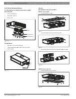
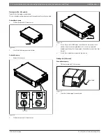
Страница 15: ...otor Figure 19 Motor Blower housing Ventilation panel Pump maintenance 1 Remove four screws from the drain pump 2 Unplug the pump power supply and water level switch cable 3 Detach the pump Figure 20 Pump 60k model Motor maintenance there are three methods Method 1 Access from top 1 Remove the top cover as shown Figure 21 2 Loosen the four bolts and two screws on the front plate Figure 22 3 Remove...

Страница 16: ...roperty damage NOTICE SYSTEM FAILURE Insulate all piping to prevent condensation which could lead to water damage If the drain pipe is bent or installed incorrectly water may leak and cause a water level switch malfunction In HEAT mode the outdoor unit will discharge water Ensure that the drain hose is placed in an appropriate area to avoid water damage DO NOT pull the drain pipe forcefully This m...

Страница 17: ...p Figure 31 39 59in 20cm 7 9in or less 55cm 21 7in or less Lean over 1 50 1 1 5m Ceiling 0 75mm 3in When connecting multiple drainpipes install the pipes as illustrated below Figure 32 53cm 20 8in or less 10cm 4in or more 4 Using a 65 mm 2 5in core drill drill a hole in the wall Make sure that the hole is drilled at a slight downward angle so that the outdoor end of the hole is lower than the indo...

Страница 18: ... the drainpipe is unobstructed Units with a pump 1 Remove the test cover Figure 35 Test cap CLOSED O P E N C L O S E D OPEN 2 Fill the water pan with 2 liters of water Figure 36 Stow tube 3 Turn on the unit in COOLING mode You will hear the drain pump Check whether the water is discharged properly a 1 minute lag is possible depending on the length of the drain pipe Check whether water leaks from t...

Страница 19: ...LING mode You will hear the drain pump Check whether the water is discharged properly a 1 minute lag is possible depending on the length of the drain pipe Check whether water leaks from the joints 4 Turn off the air conditioner and put the cap back on If drain pump needs to be disabled 1 Remove cover of E Parts box 2 Unplug the Pump pin to disable pump 3 Short connect the CN5 Figure 40 1 2 3 Vertic...

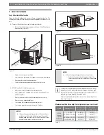
Страница 20: ...ot air discharge Near any source of combustible gas In a location that is exposed to large amounts of dust In a location exposed to excessive amounts of salty air NOTICE If the unit is exposed to heavy wind Install unit so that air outlet fan is at a 90 angle to the direction of the wind If needed build a barrier in front of the unit to protect it from extremely heavy winds See Figures 43 and 44 F...

Страница 21: ...rain joint into the hole in the base pan of the unit 3 Rotate the drain joint 90 until it clicks in place facing the front of the unit 4 Connect a drain hose extension not included to the drain joint to redirect water from the unit during heating mode If the drain joint does not come with a rubber seal see Figure 45 pos B do the following 1 Insert the drain joint into the hole in the base pan of t...

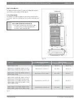
Страница 22: ... in these instructions and or local building codes Outdoor Model OutdoorUnitDimensions mm in MountingDimensions W x H x D Distance A mm in Distance B mm in BMS500 AAS009 1CSXRA 770x555x300 30 3x21 85x11 81 487 19 2 298 11 73 BMS500 AAS012 0CSXRB BMS500 AAS012 1CSXRA BMS500 AAS009 1CSXHB BMS500 AAS012 1CSXHB 800x554x333 31 5x21 8x13 1 514 20 24 340 13 39 BMS500 AAS018 1CSXRA BMS500 AAS018 1CSXHB BM...

Страница 23: ...be completely removed 1 Hold the pipe at a downward angle to prevent burrs from falling into the pipe 2 Using a reamer or deburring tool remove all burrs from the cut section of the pipe Figure 48 Pipe Reamer Point down Step 3 Flare pipe ends Proper flaring is essential to achieve an airtight seal 1 After removing burrs from cut pipe seal the ends with a piece of tape to prevent foreign materials f...

Страница 24: ...1 23 7 0 93 Ø 22 75 85N m 765 867 kgf cm 26 4 1 04 26 9 1 06 Table 9 6 Place flaring tool onto the flaring block 7 Turn the handle of the flaring tool clockwise until the pipe is fully flared 8 Remove the flaring tool and flaring block then inspect the end of the pipe for cracks and even flaring Slide the nut up to see if the flare is of proper diameter and does not interfere with the threads in the flare ...

Страница 25: ...pliance to that circuit 8 Make sure to properly ground the outdoor unit 9 Every wire must be firmly connected Loose wiring can cause the terminal to overheat resulting in product malfunction and possible fire 10 Do not let wires touch or rest against refrigerant tubing the compressor or any moving parts within the unit The signal power cable enables communication between the indoor and outdoor units...

Страница 26: ...he terminals Match the wire colors labels with the labels on the terminal block Firmly screw the u lug of each wire to its corresponding terminal Refer to the Serial Number and Wiring Diagram located on the cover of the electric control box Figure 54 Connective wiring diagram Wiring diagram Control box Magnetic ring if supplied and packed with the accessories Figure 55 1 2 3 Passthe beltthrough th...

Страница 27: ...conditioning unit is off perform the following steps Press the button COPY for a few seconds Press or to select the AF Figure 56 Press CONFIRM The air conditioning unit will then start the fan for airflow automatic adjustment Figure 57 ON will flash during when the fan is on during automatic airflow adjustment NOTICE SYSTEM FAILURE DO NOT adjust the dampers when automatic airflow adjustment is acti...

Страница 28: ...d gauge Keep the High Pressure side closed 4 Turn on the vacuum pump to evacuate the system 5 Run the vacuum until the Compound Meter reads 76cmHg 29 92 Hg 101 kPa It is recommended to use a micron gauge run the vacuum until the micron gauge reads 350 to 500 microns or less 6 Close the Low Pressure side of the manifold gauge and turn off the vacuum pump 7 Wait for approximately 10 to 15 minutes the...

Страница 29: ...culated using the following formula Additional refrigerant per pipe length ConnectivePipe AirPurging Additional Refrigerant Standard pipe length Vacuum Pump N A Standard pipe length Vacuum Pump Liquid Side Ø 6 35 ø 0 25 Inverter R410A Pipe length standard length x 15g m Pipe length standard length x 0 16oZ ft Liquid Side Ø 9 52 ø 0 375 Inverter R410A Pipe length standard length x 30g m Pipe length...

Страница 30: ...eakage During the Test Run use an electroprobe and multimeter to perform a comprehensive electrical leakage test If electrical leakage is detected turn off the unit immediately and call a licensed electrician to find and resolve the cause of the leakage This may not be required for some locations in the US WARNING Risk of electric shock All wiring must comply with local and national electrical cod...

Страница 31: ...rm the following checks ListofCheckstoPerform Pass Fail No electrical leakage Unit is properly grounded All electrical terminals are properly covered Indoor and outdoor units are solidly installed All pipe connection points do not leak Water drains properly from drain hose All piping is properly insulated Unit performs COOL function properly Unit performs HEAT function properly Indoor unit louvers...

Страница 32: ...f recyclable products Refrigerant At the end of the service life of this appliance and prior to its environmental disposal a person qualified to work with refrigerant circuits must recover the refrigerant from within the sealed system WARNING CONTAINS REFRIGERANT Improper disposal of this appliance endangers your health and is bad for the environment Hazardous substances may leak into the ground wa...

Страница 33: ...Installation Manual Bosch Climate 5000 Series Ducted Type Medium High Static Air Conditioner Heat Pump 33 Bosch Thermotechnology Corp 05 2019 Data subject to change ...

Страница 34: ...34 Bosch Climate 5000 Series Ducted Type Medium High Static Air Conditioner Heat Pump Installation Manual 05 2019 Bosch Thermotechnology Corp Data subject to change ...

Страница 35: ...Installation Manual Bosch Climate 5000 Series Ducted Type Medium High Static Air Conditioner Heat Pump 35 Bosch Thermotechnology Corp 05 2019 Data subject to change ...

Страница 36: ...United States and Canada Bosch Thermotechnology Corp 65 Grove Street Watertown MA 02472 Tel 866 642 3198 Fax 603 965 7581 www boschheatingandcooling com BTC 769003105 A 05 2019 ...

Отзывы: