background image

11

Installation/Operating Instructions

Invented for life

TEMPERATURE SELECTOR PAD INSTALLATION DETAILS

Main, Bathroom & Sub Control

Select a suitable flat, dry location away from direct sunlight.(Direct sunlight could
make it difficult to see display)
Cut an opening in wall through center of where the remote control is to be installed,
pull cable from wall cavity through opening. Attach cable to control. Remove cover
from remote control, locate control so that the wiring is not caught between the wall
and the remote control.
Secure control to wall using the screws provided and refit front cover.
Ensure that sufficient cable length is left to remove control if necessary.

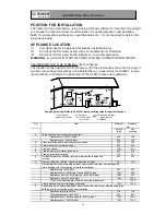
TEMPERATURE SELECTOR PAD WIRING DETAILS

1

Remove the front cover of the water heater and locate the PCB on the right hand
side of the cabinet.

2

Locate the two control terminals on the PCB. 
(Please be aware that all controller terminals connect back to the same two
points on the PCB)

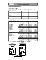
PRE-SET TEMPERATURE

The Bosch water heaters are factory pre-set to operate at 55°C (or 50°C on 50
degree model) without temperature selector pads. The pre-set temperatures can be
altered to 60°C or 75°C, (or 42°C on 50 degree limited unit) by changing the setting
of the CPU or by using the temperature bridges supplied. Refer to page 13 for
details.
The appliance can also be fitted with temperature selector pads, available as an
accessory item. When fitted, the hot water will be delivered at the temperature
displayed on the selector pad.
There are two versions of remote controls available, the 66 series which has bath fill
alarm and the 67 series which has bath fill stop. 

The two different series must never be connected to the same water heater.
The sub controller cannot be used as a sole controller. 

There is a Main, Bathroom and Ensuite control available in each series, never
connect more than one of each control type to the water heater (except an extra sub
controller as the fourth controller.)

Only one of each type can be connected to the appliance.

Main controller

YPRM67XBN

YPRM67XB

YPRM66XB

Max temperature 75° C #

Bathroom controller

YPRS67XBN

YPRS67XB

YPRS66XB

Max temperature 50°C

Ensuite controller

YPRP62XB

YPRP62XB

Max temperature 50°C

67 series (Bathstop)

66 series (Bathfill)

# MAXIMUM TEMPERATURE IS CONTROLLED BY THE MAXIMUM DEFAULT

TEMPERATURE SET IN THE WATER HEATER

Содержание ART 26 COMBITRIM

Страница 1: ...ng Water and Gas fitting regulations To be installed and serviced only by an authorised person This appliance is not suitable for use as a pool heater The authorised installing person is responsible for 1 Correct commissioning of this appliance 2 Ensure unit performs to the specifications stated on the rating label 3 Demonstrate operation of unit to customer before leaving 4 Hand these instruction...

Страница 2: ...TION 10 ELECTRICAL CONNECTION 10 PRE SET TEMPERATURE 10 TEMPERATURE SELECTOR PAD INSTALLATION 11 TEMPERATURE SELECTOR PAD WIRING 11 TEMPERATURE CONTROL OPERATION 12 COMMISSIONING AND TESTING 12 TEMPERATURE SETTING 13 USER SAFETY INSTRUCTIONS 15 IN CASE OF DIFFICULTIES 15 Manufacturer s Warranty 17 INDEX Installation Operating Instructions Invented for life ...

Страница 3: ...mperature selector pads have a maximum temperature setting of 50 C for safety To ensure compliance with Australian Standard AS NZS 3500 4 in the bathroom area this may be achieved by using a Bosch appliance limited to 50 C or using a Bosch appliance with a delivery temperature greater than 50 C and installed with a tempering valve high performance In New Zealand please refer to the New Zealand Bui...

Страница 4: ...ion Pressure relife valve and Water drain valve Earth connection screw Bottom of case Air inlet Flue terminal DIMENSIONS YS2670RA series YS2670RABZ 590 592 567 622 600 120 60 84 44 48 10 10 133 49 318 320 268 10 50 120 40 97 40 109 85 178 37 338 47 10 11 170 31 350 334 253 42 25 Power cable intaking hole Power cable intaking hole PS flame installation pich PS flame installation pich Perspective dr...

Страница 5: ...ad 20mm Relief valve pressure setting 1600 kPa DATA PLATE Fitted inside of cabinet GAS TYPE The gas type is nominated on a temporary label located on the front cover and on the data plate located inside of cabinet The gas type is the gas on which this appliance is designed to operate DO NOT OPERATE WITH ANY OTHER GAS TYPE WARNING LABELS Located on the right side of the cabinet PLEASE READ THESE LA...

Страница 6: ...00 Appliances over 200 MJ h input up to 250 MJ h input 1500 500 k Froma mechanicalair inlet including spablower 1500 1000 n Verticallybelow an openablewindow non mechanicalair inlet or any other opening into a building with the exception of sub floor ventilation Spaceheatersup to 50 MJ h 150 150 Other appliancesup to 50 MJ h 500 500 Appliancesover 50 MJ h and up to 150 MJ h input 1000 1000 Applian...

Страница 7: ...ion device Thermal fuse Over heat prevention device Burner manifold Remote Control Connections Hot water temperature change connector Ignition plug Flame rod Flame failure safety device Gas solenoid valve set Printed circuit board Water flow rate adjusting valve Gas connection Outlet water connection Power cable Inlet water connection YS1770RA series YS2170RA series ...

Страница 8: ...trol Connections Burner manifold Thermal fuse Flue terminal Antifrost heater High limit switch Earth leakage breaker Water flow rate adjusting valve Flame rod Inlet water connection Power cable Outlet water connection Gas connection Controller Remote Empty heating prevention device Over heat prevention device Flame failure safety device YS2670RA series YS2670RABZ ...

Страница 9: ...rate correctly SERVICE CALLS ARE CHARGEABLE FOR UNITS WITH INCORRECT PIPE SIZES OR BLOCKED GAS OR WATER FILTERS COLD WATER CONNECTION TO WATER HEATER Refer to technical sheet for position of connections The WATER INLET connection is 20 mm 3 4 BSP and requires a union to allow for removal of the water heater Pipe sizing from the cold water supply should be sized according to local BY LAWS for water...

Страница 10: ...n the O ring seal In order to comply with AS3498 the minimum distances as per the diagram below must be observed These requirements are only for the 50 C locked units WARNING For continued safety of this appliance it must be installed operated and maintained in accordance with the manufacture s instructions ELECTRICAL CONNECTION The appliance is equipped with a 1 7 metre cable with a three pinned ...

Страница 11: ...without temperature selector pads The pre set temperatures can be altered to 60 C or 75 C or 42 C on 50 degree limited unit by changing the setting of the CPU or by using the temperature bridges supplied Refer to page 13 for details The appliance can also be fitted with temperature selector pads available as an accessory item When fitted the hot water will be delivered at the temperature displayed...

Страница 12: ...as inlet pressure and remove manometer Retighten test point and soap test Test operation of the appliance explain operation to consumer hand over these installation instructions Please leave your contact details with the consumer BURNER PRESSURE ADJUSTMENT No adjustment should be necessary providing the gas inlet pressure is correct Burner pressure adjustment is necessary when converting to a diff...

Страница 13: ...ory Setting 37 55 C Bridge B 37 60 C 37 50 C 37 50 C Bridge A 37 75 C 37 50 C Remote controller YPRM66XB YPRS66XB 37 55 C 37 60 C 37 75 C YPRM67XBN 37 50 C 37 50 C 37 50 C YPRS67XBN 37 50 C 37 50 C 37 50 C YPRP62XB 37 50 C 37 42 C 37 50 C 37 42 C 37 50 C 37 50 C YPRM66XB YPRS66XB 37 50 C 37 42 C 37 50 C YPRM67XBN 37 50 C 37 42 C 37 50 C YPRS67XBN 37 50 C 37 42 C 37 50 C YPRP62XB YS1770RA5 YS2170RA...

Страница 14: ...for life Step 2 Turn off power to unit Step 3 Insert bridge into plastic clip between the controller terminals Step 4 Turn power back on Unit is now set as per the table on the previous page PCB Controller Switch Modulation Adjust Setting Remote A B ...

Страница 15: ...not operate burns with yellow flame leaks water or a gas smell is evident turn off and contact the local gas authority the manufacturer or an authorized service person 6 In cases where the inlet water temperature is greater than 20 C the flow rate will need to be increased to maintain low temperatures if using a temperature controller IN CASE OF DIFFICULTIES If the Bosch water heater ceases to ope...

Страница 16: ...d acceptable and generally Australian and New Zealand suburban water supplies fall within these limits parameters In areas of Australia and New Zealand where water may be supplied either fully or partly from bores artesian wells or similar one or more of the important limits may well be exceeded and the heater could therefore be at risk of failure Where uncertainty exists concerning water quality ...

Страница 17: ...it for purposes other than which it was designed or approved d unauthorised repairs or alterations to the unit without Bosch s consent e use of unauthorised parts and accessories without Bosch s consent f use of non potable water or bore water in the hot water unit see product instructions for further details g continued use after a fault becomes known or apparent This warranty DOES NOT include a ...

Страница 18: ...collected during warranty claims may be used for the provision of customer support for the provision of information about products and services and for other marketing activities undertaken by Bosch and its Bosch Service Agents who are authorised to carry out warranty repairs on behalf of Bosch Purpose Bosch is committed to protecting the privacy of its customers personal information It will act i...

Отзывы: