Bosch 7629130 Скачать руководство пользователя страница 3

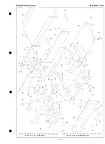
Zerlegungs- und Reparaturhinweise

1. Abnehmen des 

a) Die zwei Schrauben an beiden 

entfernen.

b) Den Gehausedeckel 


 herausziehen.

2. Abnehmen der Frontplatte

a) Die Drehknopfe des TAPE-SELECT-Schalters

und des LEVEL-Reglers abziehen.

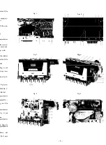
b) Die Schrauben 1-3 (Fig. 1) entfernen.
c) Die Schrauben l-5 (Fig. 2) entfernen.

d) Die beiden Randelschrauben mit der 

tenblende entfernen.

e) Die Frontplatte herausziehen.

3. Abnehmen der Bodenplatte

a) Die Schrauben 1-6 sowie 9-14 (Fig. 2) 

b) Die Bodenplatte abnehmen.

4. Ausbau des Laufwerks

a) Gerat 

 Ziffer 2 und 3 zerlegen.

b) Die Schrauben 7 und 8 (Fig. 2) entfernen.
c) 

 des A/W-Kopfes an der 

platine abloten, 

 des Lbschkopfes 

ziehen.

d) Zuleitungskabel am Laufwerk 
e) Die Schraube 4 (Fig. 1) entfernen.
g) Die Schraube 3 (Fig. 6) entfernen.
h) Den Reedkontakt 

 der Gummihalterung

nehmen.

i) Den Bowdenzug laufwerksseitig abnehmen.
k) Das Laufwerk 


 herausnehmen.

5. Ausbau von Cassettenfach und Blende

a) Sicherungsscheiben 6, 10 (Fig. 4) sowie die

 7 entfernen.

b) Die Schraube 9 (Fig. 4) entfernen und den

 (Fig. 4) 

c) Cassettenfach 

 und entfernen.

d) Die Schrauben 1, 2 (Fig. 4) und 2 (Fig. 6) 

e) Blende 

 und entfernen.

6. Ausbau des Antriebsmotors

a) Laufwerk 

 Ziffer 5 zerlegen.

b) Die Schrauben 3-5 (Fig. 4) sowie 3 (Fig. 5)

entfernen.

c) Antriebsriemen 

 und Motor 

nehmen.

7. Ausbau der Capstanwelle

a) Gerat 

 Ziffer 5 zerlegen.

b) Die Schrauben 4, 5 (Fig. 5) sowie 1 (Fig. 6) 

c) Lagerschild abnehmen und Capstanwelle 

ausziehen.

8. Ausbau der Andruckrolle

a) Gerat 

 Ziffer 2 zerlegen.

b) Sicherungsscheibe 1 (Fig. 3) entfernen und

Andruckrolle abziehen.

9. Ausbau des A/W-Kopfes

a) Gerat 

 Ziffer 2 zerlegen.

b) Die zwei Halteschrauben entfernen.

c) 

 Austausch des A/W-Kopfes ist der 

muthwinkel neu einzustellen (Ziffer 4, Seite 5).

10. Ausbau der Wickelteller

a) Gerat 

 Ziffer 4 und 5 zerlegen.

b) Halteklammern 1, 2 (Fig. 5) aufbiegen und 

kelteller abziehen.

Disassembly and Repair Hints

1 .

Removal of chassis cover

a) Remove the two screws on either side of the

cassette deck.

b) Remove chassis cover to the rear.

2 .

Removal of front panel

a) With draw the rotary knobs of the TAPE-SE-

LECT switch and of the LEVEL control.

b) Remove screws 1-3 (Fig. 1).
c) Remove screws l-5 (Fig. 2).
d) Remove the two knurled screws with the cas-

sette mask.

e) Pull out front panel.

3 .

Removal of bottom plate

a) Remove screws l-6 and 9-14 (Fig. 2).
b) Remove bottom plate.

4 .

Removal of drive mechanism

a) Disassemble the cassette deck in accordance

with Items 2 and 3.

b) Remove screws 7 and 8 (Fig. 2).
c) Unsolder the connecting cable of the record-

ing/playback head at the main PC board and

pull off the erasure head connector.

d) Unsolder the feed-in cable at the drive motor.
e) Remove screw No. 4 (Fig. 1).
g) Remove screw No. 3 (Fig. 6).

h) Remove the Reed contact from the rubber

mounting.

i) Remove the 

 cable at the side of the

drive motor.

h) Remove the drive mechanism to the rear.

5 .

Removal of the cassette bay and mask

a) Remove locking washers 6 and 

 (Fig. 4) and

sleeve No. 7.

b) Remove screw No. 9 (Fig. 4) and unhinge lever

No. 8 (Fig. 4).

 Unhinge and remove cassette bay.

d) Remove screws 1 and 2 (Fig. 4) and No. 2

(Fig. 6).

e) Unhinge and remove mask.

6 .

Removal of the drive motor

a) Disassemble the drive mechanism in accord-

ance with Item 5.

b) Remove screws 3-5 (Fig. 4) and screw No. 3,

(Fig. 5).

c) Remove the drive belt and take the motor out.

7 .

Removal of capstan shaft

a) Disassemble the cassette deck in accordance

with Item 5.

b) Remove screws 4 and 5 

 screw No. 

(Fig. 6).

c) Remove the bearing plate and pull out the

capstan shaft.

8 .

Removal of rubber pinch roller

a) Disassemble the equipment in accordance

with Item 2.

b) Remove the locking washer No.1 (Fig. 3) and

pull off the rubber pinch roller.

9 .

Removal of the recording/playback head

a) Disassemble the cassette deck in accordance

with Item 2.

b) Remove the two mounting screws.
c) Readjust the Azimuth angle (Item 4, Page 5)

after replacement of the recording/playback

head (Fig. 4, Page 5).

10.

Removal of the spindels

a) Disassemble the equipment in accordance with

Item 4 and 5.

b) Bend open holding clamps 1 and 

 5)and

pull off spindle.

Содержание 7629130

Страница 1: ...eilliste Gerat Explosionszeichnung Gerat Ersatzteilliste Laufwerk Explosionszeichnung Laufwerk Seite 2 3 4 5 7 8 9 IO 1 1 12 13 14 15 Table of Contents Technical Data Disassembly and Repair Hints Test and Alignment Hints Component Plan Circuit Diagram Spare Parts List El Components Spare Parts List Cassette Deck Exploded View Cassette Deck Spare Parts List Drive Mechanism Exploded View Drive Mecha...

Страница 2: ...te Blaupunkt HiFi units exceed the values claimed for in DIN 45500 The sets are provided with the VDE sign thus fulfilling the common VDE stipulations to be observed for any repair All components marked by A have to be replaced by original parts Wert Value 220 V 50 Hz Belt Drive 4 75 cmlsec 1 f 0 2 30Hz 15kHz 30Hz 16kHz Dolby B 64dB 56dB 65dB 57dB 66dB 58dB 37dB 15 dB 13 dB 15 dB 0 2 mV 2 2 kB 3 m...

Страница 3: ... und Wik kelteller abziehen Disassembly and Repair Hints 1 Removal of chassis cover a Remove the two screws on either side of the cassette deck b Remove chassis cover to the rear 2 Removal of front panel a With draw the rotary knobs of the TAPE SE LECT switch and of the LEVEL control b Remove screws 1 3 Fig 1 c Remove screws l 5 Fig 2 d Remove the two knurled screws with the cas sette mask e Pull ...

Страница 4: ...he record board and e motor 9 Fig 2 the rubber side of the rear Fig 4 and hinge lever and No 2 in accord rew No 3 iotor out accordance icrew No 1 ull out the accordance Fig 3 and ad accordance 4 Page 5 g playback Fig 3 Fig 5 Fig 6 dance with Fig 5 an d 4 ...

Страница 5: ...ts all parts contacting the tape e g magnetic heads guidings capstan etc have tobe demagnetized The alignment tools have to con sist of non magnetizable material Clean rubber pinch roller and mirrors of head with alcohol if necessary Attention Filters L 201 and L 202 must not be tuned Measurement equipment required 1 Audio frequency oscillator 30 Hz 20 kHz 0 5 V output 2 Voltmeter with r m s value...

Страница 6: ...uenzgang mit CrO2 und FeCr Bezugsband kontrollieren Das Toleranz feld mu8 such bei Dolby Betrieb eingehalten werden g Der Frequenzgang kann mit VR 301 302 gege benenfalls korrigiert werden siehe Ziffer 8 Fe203 Fig 7 c d 30Hz 250Hz IOkHz 12 5kHz 10 DOLBY Abgleich a Prufaufbau gema Fig 10 erstellen b NF Generator auf 5 kHz 0 5 V Output einstel len c DIN Bezugscassette Fe203 einlegen und TAPE SELECT ...

Страница 7: ...Fig 8 blau blue Fig 9 Fig 10 G L 22 Cassettendeck i 70k I 1 1 7 ...

Страница 8: ...Bestiickungsplan Component Plan MICROPHONE RECORD PLAYBACK BB VR103 VRlDC 55 MUNG SW Dolby PLAY FF AUIO 511 RWD Loschkopf Erasehead 8 ...

Страница 9: ...Schaltbild I I 32 7k Hauptplatte Ma board ...

Страница 10: ...Circuit Diagram Anzeigeplatte D sploy board I R I T I I 0505 s 4 RfC 0 t I 4 R50 I d 70 R5I c 560 2 I sa R5Q It R5Q It IR Lc5o3 T Q Blockschaltblld Block Clrcult Dugram ...

Страница 11: ...018 06 D 106 203 204 HZ 18 B2 D 4 0 8 8 905 405 241 O D RV 06 D 406 407 409 8 905 406 002 O B D410 W06A D401 405 8 905 406 101 L E D EinzeUSingle rot red D 5 0 5 8 905 405 365 O H L E D Einzel Single grtin green D 5 0 6 8 905 405 363 A0 L E D 2fach 2 fold rot red D 502 504 4L 8 905 405 369 A G L E D 4fach 4 fold grtin green D 501 503 8 905 405 367 DF 5 kOhm VR 105 106 8 901 499 022 O F 1 0 kOhm VR...

Страница 12: ... Holder Carrier plate Mask Colour Filter Cassette b a y Frame Spring Spring Holder Damper Key RECORD A n g l e k e y Angle Carrier plate Mains transformer Soldering terminal Chassis side part Diode connector Traction relief Power cable Traction relief Bowden cable Key button Key button Front panel Rotary knob Rotary knob Switch knob Mask Screw Botton plate Screwed on foot Chassis cover Reed contac...

Страница 13: ...eichnung Exploded View Hinweis Die Zahlen in der Explosionszeichnung entsprechen der Lfd Nr in der Ersatzteilliste Note The numbers in the exploded view correspond with the Item No given in thespare parts list 13 ...

Страница 14: ...Head carrier Head carrier Recording Playback Erasure head Rubber pinch roller Spindle Drive roller Spindle Drive roller Slide Support plate Support Gyrating mass Slide Lever Slide Angle Drive motor Drive axle Drive belt Motor mount Slide Key mechanism Slide Lever Lever Brake Counter Counter support Belt Switch Angle Spring Electromagnet Lever Switch Screws Washers Springs Spare Parts List Preis Be...

Страница 15: ... Exploded View 1 1 6 1 7 8 324 I Hinweis Die Zahlen in der Explosionszeichnung entsprechen der Lfd Nr in der Ersatzteilliste Note The numbers in the exploded view correspond with the Item No given in the spare parts list 15 ...

Отзывы: