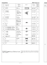
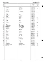
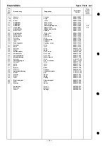
Bosch 7629130 Скачать руководство пользователя страница 14

Ersatzteilliste

Lfd.

Nr.

Bezeichnung

Item

N o .

1 0 1

Chassis

1 0 4

W i n k e l

1 0 6

Hebel

1 1 0

Kopftrager

1 1 1

Kopftrager

1 1 6

A/W-Kopf

1 1 7

 kopf

1 2 1

Andruckrolle

1 2 4

Wickelteller

1 2 5

Antriebsrolle

128

Wickelteller

1 3 0

Antriebsrolle

1 3 3

Schieber

1 3 5

Lagerblech

1 3 6

Lager

1 3 9

Schwungmasse

1 4 1

Schieber

1 4 3

Hebel

1 4 4

Schieber

1 4 6

W i n k e l

1 4 8

Antriebsmotor

1 4 9

Antriebsachse

1 5 0

Antriebsriemen

1 5 1

Motorhalterung

1 5 5

Schieber

1 5 9

Tastenaggregat

1 6 1

Schieber

164

Hebel

1 6 7

Hebel

1 7 1

Bremse

1 7 4
1 7 5

Zahlwerkhalterung

176

Riemen

1 7 8

Schalter

1 7 9

W i n k e l

1 8 0

Feder

1 8 5

Elektromagnet

1 8 6

Hebel

1 8 7

Schalter

Schrauben
Scheiben
Federn

Designation

Chassis
Angle

L e v e r

Head carrier
Head carrier
Recording/Playback

Erasure head
Rubber pinch roller

Spindle

Drive roller

Spindle
Drive roller

S l i d e
Support plate
Support

Gyrating mass
S l i d e
L e v e r

S l i d e

Angle

D r i v e   m o t o r

Drive axle
Drive belt
Motor mount

S l i d e
Key mechanism
S l i d e

L e v e r
L e v e r
Brake

Counter
Counter support
Belt

Switch

Angle

Spring

Electromagnet
L e v e r
Switch

S c r e w s
W a s h e r s
Springs

Spare Parts List

Bestell-Nr.

P a r t   N o .

8629107027
8629117125
8629117126

8629117127
8629117128
8629137600

K N

8629137601

C E

8629117212
8629117213

8629117214
8629117215
8629117216

8629117217
8629117129
8629117130

8629117218
8629117131
8629117132

8629117133
8 629 127 216
8629127402

8629117219
8629117905
8629117134

8 629 117 135
8 629   27 235
8629117136

8629117137
8629117138
8629117139

8629127410
8 629 117 140
8 629 117 906

8629117141
8629117142
8629117610

8629137024
8629117143
8629127226

8627000570
8627000571
8627000572

 14

Содержание 7629130

Страница 1: ...eilliste Gerat Explosionszeichnung Gerat Ersatzteilliste Laufwerk Explosionszeichnung Laufwerk Seite 2 3 4 5 7 8 9 IO 1 1 12 13 14 15 Table of Contents Technical Data Disassembly and Repair Hints Test and Alignment Hints Component Plan Circuit Diagram Spare Parts List El Components Spare Parts List Cassette Deck Exploded View Cassette Deck Spare Parts List Drive Mechanism Exploded View Drive Mecha...

Страница 2: ...te Blaupunkt HiFi units exceed the values claimed for in DIN 45500 The sets are provided with the VDE sign thus fulfilling the common VDE stipulations to be observed for any repair All components marked by A have to be replaced by original parts Wert Value 220 V 50 Hz Belt Drive 4 75 cmlsec 1 f 0 2 30Hz 15kHz 30Hz 16kHz Dolby B 64dB 56dB 65dB 57dB 66dB 58dB 37dB 15 dB 13 dB 15 dB 0 2 mV 2 2 kB 3 m...

Страница 3: ... und Wik kelteller abziehen Disassembly and Repair Hints 1 Removal of chassis cover a Remove the two screws on either side of the cassette deck b Remove chassis cover to the rear 2 Removal of front panel a With draw the rotary knobs of the TAPE SE LECT switch and of the LEVEL control b Remove screws 1 3 Fig 1 c Remove screws l 5 Fig 2 d Remove the two knurled screws with the cas sette mask e Pull ...

Страница 4: ...he record board and e motor 9 Fig 2 the rubber side of the rear Fig 4 and hinge lever and No 2 in accord rew No 3 iotor out accordance icrew No 1 ull out the accordance Fig 3 and ad accordance 4 Page 5 g playback Fig 3 Fig 5 Fig 6 dance with Fig 5 an d 4 ...

Страница 5: ...ts all parts contacting the tape e g magnetic heads guidings capstan etc have tobe demagnetized The alignment tools have to con sist of non magnetizable material Clean rubber pinch roller and mirrors of head with alcohol if necessary Attention Filters L 201 and L 202 must not be tuned Measurement equipment required 1 Audio frequency oscillator 30 Hz 20 kHz 0 5 V output 2 Voltmeter with r m s value...

Страница 6: ...uenzgang mit CrO2 und FeCr Bezugsband kontrollieren Das Toleranz feld mu8 such bei Dolby Betrieb eingehalten werden g Der Frequenzgang kann mit VR 301 302 gege benenfalls korrigiert werden siehe Ziffer 8 Fe203 Fig 7 c d 30Hz 250Hz IOkHz 12 5kHz 10 DOLBY Abgleich a Prufaufbau gema Fig 10 erstellen b NF Generator auf 5 kHz 0 5 V Output einstel len c DIN Bezugscassette Fe203 einlegen und TAPE SELECT ...

Страница 7: ...Fig 8 blau blue Fig 9 Fig 10 G L 22 Cassettendeck i 70k I 1 1 7 ...

Страница 8: ...Bestiickungsplan Component Plan MICROPHONE RECORD PLAYBACK BB VR103 VRlDC 55 MUNG SW Dolby PLAY FF AUIO 511 RWD Loschkopf Erasehead 8 ...

Страница 9: ...Schaltbild I I 32 7k Hauptplatte Ma board ...

Страница 10: ...Circuit Diagram Anzeigeplatte D sploy board I R I T I I 0505 s 4 RfC 0 t I 4 R50 I d 70 R5I c 560 2 I sa R5Q It R5Q It IR Lc5o3 T Q Blockschaltblld Block Clrcult Dugram ...

Страница 11: ...018 06 D 106 203 204 HZ 18 B2 D 4 0 8 8 905 405 241 O D RV 06 D 406 407 409 8 905 406 002 O B D410 W06A D401 405 8 905 406 101 L E D EinzeUSingle rot red D 5 0 5 8 905 405 365 O H L E D Einzel Single grtin green D 5 0 6 8 905 405 363 A0 L E D 2fach 2 fold rot red D 502 504 4L 8 905 405 369 A G L E D 4fach 4 fold grtin green D 501 503 8 905 405 367 DF 5 kOhm VR 105 106 8 901 499 022 O F 1 0 kOhm VR...

Страница 12: ... Holder Carrier plate Mask Colour Filter Cassette b a y Frame Spring Spring Holder Damper Key RECORD A n g l e k e y Angle Carrier plate Mains transformer Soldering terminal Chassis side part Diode connector Traction relief Power cable Traction relief Bowden cable Key button Key button Front panel Rotary knob Rotary knob Switch knob Mask Screw Botton plate Screwed on foot Chassis cover Reed contac...

Страница 13: ...eichnung Exploded View Hinweis Die Zahlen in der Explosionszeichnung entsprechen der Lfd Nr in der Ersatzteilliste Note The numbers in the exploded view correspond with the Item No given in thespare parts list 13 ...

Страница 14: ...Head carrier Head carrier Recording Playback Erasure head Rubber pinch roller Spindle Drive roller Spindle Drive roller Slide Support plate Support Gyrating mass Slide Lever Slide Angle Drive motor Drive axle Drive belt Motor mount Slide Key mechanism Slide Lever Lever Brake Counter Counter support Belt Switch Angle Spring Electromagnet Lever Switch Screws Washers Springs Spare Parts List Preis Be...

Страница 15: ... Exploded View 1 1 6 1 7 8 324 I Hinweis Die Zahlen in der Explosionszeichnung entsprechen der Lfd Nr in der Ersatzteilliste Note The numbers in the exploded view correspond with the Item No given in the spare parts list 15 ...

Отзывы: