


UPSaver
installation and start-up
OMH44149 REV. C
39
3.4
SYSTEM POSITIONING AND INSTALLATION
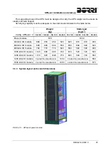
3.4.1 Positioning the I/O module
The
UPSaver
system can be positioned on an iron base specifically prepared and placed on
the base of a floating floor. In this case the space underneath the UPS bearing surface is used
as a opening to where the interconnection cables between the I/O module and the power
modules can be laid.
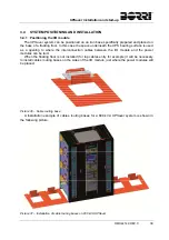
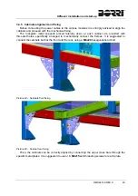
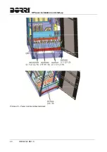
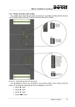
When the floating floor is not installed (for top cables entry for example) it will be necessary
to install cables routing bases on the sides of the I/O module, just where the power modules will
be placed.
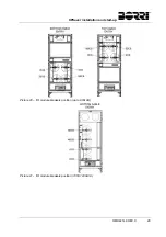
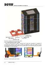
Picture 36 – Cable routing base
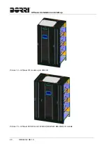
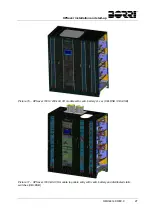
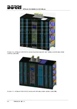
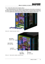
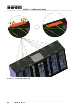
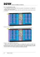
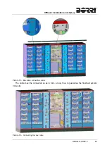
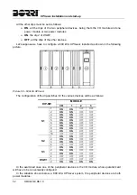
A Installation example of cables routing bases for a 800 kVA
UPSaver
system is shown in
the following picture.
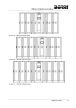
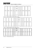
Picture 37 – Installation of cable routing bases on 800 kVA UPSaver
Содержание UPSaver 1000 kVa
Страница 2: ...UPS OPERATING MANUAL UPSaver 400 1600 kVA ...
Страница 5: ......
Страница 7: ...Warnings and general information 2 OMH44148 REV A ...
Страница 13: ......
Страница 20: ...UPSaver installation and start up OMH44149 REV C 7 ...
Страница 33: ...UPSaver installation and start up 20 OMH44149 REV C Picture 6 Handling of the power module ...
Страница 57: ...UPSaver installation and start up 44 OMH44149 REV C Picture 46 UPS cabinets upper fixing ...
Страница 59: ...UPSaver installation and start up 46 OMH44149 REV C Picture 49 Power module cables terminals ...
Страница 115: ...UPS user manual 6 OMH44150 REV B ...