background image


17 

We reserve all rights of ownership and exploitation in respect of these 
documents, including industrial property rights. These documents may only 
be used with our express consent in writing, and only to the extent permitted 
in any such consent. The documents may not be duplicated or made 
available to third parties. In case of violation of the aforementioned 
provisions, we reserve all rights. 

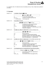
10.1.4 Operating modes 

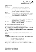
Simulation 

Current simulation:


In order to test the devices connected in series, a fixed output  


current of 3.9 to 22 mA can be set. After the test, the current value 


0 mA must be entered to end simulation. 

Alarm 21.8 mA: 

An alarm signal can be transmitted via the current loop. 


The current then rises to 21.8 mA. This alarm is generated due to a 


maloperation of the DIMF. The alarm function can be switched off. 

Selection of 
measured variable:


The measured variable has been assigned to the HART

 primary variable and 


thus to the current output. When displaying density, the user can change 


between operating or reference density. When calculating the concentration,  


the user can select between the two different methods. 


10.1.5 Special settings 

Electronic adjustment 

Calibrate current output: The characteristic of the analog current output can be calibrated in its zero 
 

point at 4 mA and in its slope at 20 mA. It must be observed that the zero point 


will be calibrated before the upper range value. 

Reset device:


With this command, the device can be restored to a defined operating state 


present after the supply voltage was applied. 

10.2  Operation with the keys (configuration via the control unit) 

To access the keys, the screw cover of the longer end of the housing must be opened. When the housing 
cover has been opened, the degree of protection of the housing is not ensured. 
After the configuration has been completed, the housing cover must be remounted and the screws must 
be fastened fingertight (be careful not to damage the sealing ring). 

For the Exd version the housing may only be removed after it has been ensured that 
there is no explosive atmosphere.  

The covers of the Exd version are secured against opening. In order to open the cover, the locking bar 
must be swiveled sideways and clamped in this position. After closing the covers, they must be 
resecured. 

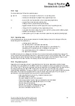
10.2.1 Display 

The transmitter type TR has a two-line display with 8 digits for each line. Each line is subdivided into two 
fields: 


- in the 1

st

 field the channel no. is displayed (1 digit) 


- in the 2

nd

 field the corresponding measured values  


  or the constants are displayed (7 digits). 

The values displayed in the upper line cannot be changed. The values displayed in the lower line 
(programming line) can be changed. 
The activated line is marked with a triangle behind the channel number. By pressing the ENTER key, you 
can toggle between the lines. 

!


Содержание DIMF 2.0 TVS

Страница 1: ... www burmt de info burmt de Änderungen der Abmessungen Gewichte und anderer technischer Daten vorbehalten Printed in the Federal Republic of Germany BA 06730 01 01 e Rev no 01099 003 Page 1 of 30 Density Transducer DIMF 2 0 TVS for continuous measurement of density and concentration of liquids with HART Communication Operating Instructions ...

Страница 2: ... with sampling and sight glass 9 4 1 4 with sampling and calibration or flushing connection 9 4 2 Installation into the product line 10 4 3 Examples for installation positions 10 5 Mounting 10 5 1 Density transducer 10 5 2 Piping 11 5 3 Process connections 11 5 4 Relationship between permissible ambient temperature and temperature of liquid 11 6 Electrical connection 12 6 1 Power supply voltage 12...

Страница 3: ...the control unit 19 10 3 Channel overview channel assignment 20 11 Equations 21 12 Maintenance 22 13 Error detection troubleshooting 22 13 1 Errors defects caused by the liquid 23 13 2 Errors defects caused by the transmitter 24 13 2 1 Error code table 25 13 3 Errors defects caused by the density transducer 25 14 Self monitoring functions 26 14 1 Monitoring supply voltage 26 14 2 Error message 26 ...

Страница 4: ...nized II Warranty For the scope and period of warranty please refer to the contractual terms of delievery Claims under warranty shall be conditional to expert installation and startup in compliance with the operating instructions for the device The electronics contains electrostatically sensitive parts Therefore electrostatic discharges must be avoided when the electronics housing is open III Gene...

Страница 5: ...e Configuration Data Sheet supplied Temperature influence without approx 2 8 kg m C compensation Temperature compensation via integral Pt1000 in acc with DIN Class A directly in the transmitter Pressure influence less than 0 02 kg m bar Operating pressure 100 bar Standard see Configuration Data Sheet supplied Liquid pumpable liquids see Configuration Data Sheet supplied Material wetted parts 1 457...

Страница 6: ...l Operation using a PC or laptop equipped with the SensorPort 2 configuration software together with the HART interface or operation using a HART hand held terminal 2 3 HC 275 of Rosemount Output signal 4 20 mA linearized and temperature corrected can be assigned to any display parameter e g operating density reference density concentration Brix Plato or other magnitudes derived from density Power...

Страница 7: ...ate and also at flow rate zero Their application is therefore normally problem free Care must however be taken to ensure that the operating flow rate in the transducer updates the sample fast enough equalizes the temperature in the tranducer avoids air or gas bubbles or deposits in the oscillating tube does not cause cavitation in the oscillating tube does not cause wear through abrasives Recommen...

Страница 8: ...continuously through this element Excited electromagnetically by an excitation coil it will oscillate at its natural frequency Changes in the density of the liquid lead to changes in the natural frequency This change in frequency sensed by a pick up coil represents the measurement effect An additional built in resistance thermometer measures the process temperature which can also be used to equali...

Страница 9: ...se of violation of the aforementioned provisions we reserve all rights 4 1 2 with sampling 4 1 3 with sampling and sight glass 4 1 4 with sampling and calibration or flushing connection Part Qty Shut off valve ø12 Straight tube fitting ø12 T type connector ø12 Screw cap ø12 3 2 1 1 Part Qty Shut off valve ø12 Straight tube fitting ø12 T type connector ø12 Screw cap ø12 4 2 2 2 Part Qty Sight glass...

Страница 10: ...The device may be mounted in any position However depending on the properties of the liquid and the flow velocity the following positions are recommended Mounting position A standard mounting position e g for clean liquids at low flow velocities Mounting position B self draining position Mounting positions C or D for liquids with solids 5 Mounting 5 1 Density transducer Handle with care do not kno...

Страница 11: ...oduct line is in horizontal position By pass pipes should be as short as possible If necessary provide both heat insulation and flushing connections the latter close to the density transducer 5 3 Process connections Ensure that the density transducer connection is compatible with the by pass connections For the connection type of your density transducer see the Configuration Data Sheet supplied 5 ...

Страница 12: ...age The transmitter type TR must be supplied with 24 V DC 2 wire technique Terminal voltage 14 to 30 V DC terminals 1 and 2 Recommendation 2 wire cables twisted and shielded cable diameter 6 12 mm Ground cable shield according to section 16 1 Wiring diagram In order to ensure safe HART communication the limits for the minimum load with RL 250 Ω must be observed For the maximum amount of line and l...

Страница 13: ...lly safe supply unit or by safety barriers In order to connect the bonding conductor safely use the internal and external bonding connector terminals which have been designed for a wire range of 1 5 mm inside or 4 mm outside If barriers are part of the supply circuit they must also be connected to the common bonding conductor 7 Commissioning Flush product lines before connecting the density transd...

Страница 14: ...lue 7360 708 Kg m setpoint K0 value K0 current misalignment correct K0 value 7360 708 Kg m 0 6 Kg m 7361 308 Kg m Now this value must be entered into the transmitter type TR If possible the constants K1 and K2 should not be modified by the user Depending on the operating mode or application and the reason for the error the adjustment can also be carried out via the concentration coefficient KX0 He...

Страница 15: ...yed as a percentage of the measuring range current span Display current The setpoint value of the present current output is displayed in mA 10 1 2 Diagnosis Communication status Device address The device address for polling operation can be assigned a value between 1 and 15 Address 0 means analog operation address 0 means polling operation If the DIMF is to be installed in a multidrop system the a...

Страница 16: ...ssage A short text of 32 characters can be entered by the user or be read Write protection The DIMF does not support write protection Manufacturing no sensor The manufacturing number of the sensor can be read Manufacturing no device The manufacturing number of the device can be read It is identical with the sensor manufacturing number Revision levels universal standard software hardware The revisi...

Страница 17: ... slope at 20 mA It must be observed that the zero point will be calibrated before the upper range value Reset device With this command the device can be restored to a defined operating state present after the supply voltage was applied 10 2 Operation with the keys configuration via the control unit To access the keys the screw cover of the longer end of the housing must be opened When the housing ...

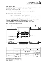
Страница 18: ...ayed in the upper line the current temperature C is displayed in the lower line the upper line is activated If a different value is to be displayed in the lower line the lower line must be activated by pressing Then you select the corresponding channel no see table in section 10 3 by pressing or Once the last channel number has been reached the display moves back to the first channel Once the firs...

Страница 19: ... see section 11 there is a choice between operating density or reference density depending on the α value concentration in for equation 1 2 4 and 5 see section The analog output signal 4 to 20 mA can be freely assigned to the desired measuring range lower range value channel 5 upper range value channel 6 within the meter range The minimum measuring range span should not be below a density range of...

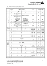
Страница 20: ...rtional to density Current output Proportional to concentration mA 4 20 2 Oscillating frequency Oscillating frequency Hz 0 5 10000 3 Temperature Temperature C 50 210 Display parameters 4 Density a percentag of measuring range span Concentration C 0 10000 5 ρmin Cmin kg m or 0 0 10000 Measur ing range 6 ρmax Cmax kg m or 0 1 10000 7 K0 kg m 100000 100000 8 K1 kg m s 100000 100000 9 K2 kg m s2 10000...

Страница 21: ...sity ρB Uncorrected operating density KT0 KT1 Transducer constants programmable t Operating temperature C measured using Pt 1000 tKal Calibration temperature Equation no 3 Calculation on reference temperature for density operating mode ρRef ρBT α t tRef ρRef Reference density ρBT Temperature corrected operating density α Expansion coefficient of the liquid programmable t Operating temperature C me...

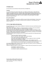
Страница 22: ...ut possible error sources These checks can normally be limited to a comparison between the measured value and a reference measurement using either lab equipment or a density transducer as a master For this purpose it is essential that the test equipment is of sufficient reliability and accuracy e g test equipment approved by the Weights and Measurement Authorities to ensure correct results During ...

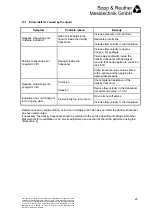
Страница 23: ...ush away sediments inside the density transducer with detergent ensure that wetted parts are corrosion resistant Positive measuring error Long term drift Deposits inside the transducer Clean transducer pipe various times with a sphere and by applying the appropriate pressure Corrosion Check material resistance of the density transducer Negative measuring error Long term drift Abrasion Reduce flow ...

Страница 24: ...t bonding conductor in cable gland Display blinks constantly Power supply voltage too low Supply voltage must be 14 V DC at the terminal Power supply voltage too low Check supply voltage Empty display Transmitter is defective Replace transmitter Channel shows error number see error code table section 13 2 1 Wrong parameterization e g wrong unit for temperature coefficient alpha Check the programme...

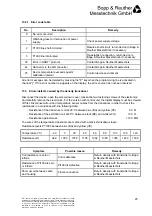
Страница 25: ... re appears on the display the error source has not been resolved 13 3 Errors defects caused by the density transducer Disconnect the device open the screw down cover loosen the two fastening screws of the electronics and carefully remove the electronics For the version with control unit the digital display must be screwed off first Disconnect all coil and temperature sensor cables from the transd...

Страница 26: ...visions we reserve all rights 14 Self monitoring functions 14 1 Monitoring supply voltage After a power failure a power ON reset will be carried out and the error code 1 will be displayed in channel or the error will be reported via HART 14 2 Error message An error code will be displayed on channel The error that was reported last will be displayed For the corresponding error description see secti...

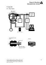
Страница 27: ...licated or made available to third parties In case of violation of the aforementioned provisions we reserve all rights 16 Appendix 16 1 Wiring diagram 2 TP 1 3 1 2 3 4 Transmitter power supply unit HART 15 to 30V RLmin 250ς Test circuit V HART Communicator 4 to 20mA HART Interface DIMF density transducer measurement of density and Not used SensorPort Grounding the cable shield Detail A A Braided s...

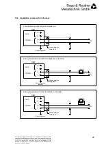
Страница 28: ...of the aforementioned provisions we reserve all rights 16 2 Application examples for safe areas Indicator 24V 4 3 2 1 External ground terminal Ground shield in cable gland 0 0 0 24V 4 3 2 1 Ground shield in cable gland External ground terminal 24V 4 3 2 1 Ground shield in cable gland External ground terminal Indicator 0 0 0 250ς DIMF Local indication without signal transmission DIMF Analog transmi...

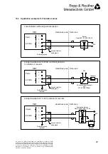
Страница 29: ...upply unit P F KFD2STC3Ex1 1 7 8 24V 9 Barrier Steel 9001 01 280 100 10 or similar Hazardous area Safe area 2 1 External ground terminal DIMF Local indication without signal transmission Pulse 4 3 2 1 24V 4 3 Ground shield in cable gland 4 20mA Hazardous area Safe area 2 1 External ground terminal DIMF Analog transmission 4 to 20mA electrically isolated to indicator or recorder Pulse 4 3 Ground sh...

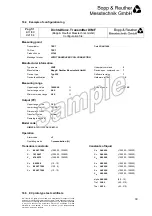
Страница 30: ...opp Reuther Messtechnik GmbH Device spec command rev 7 Device type Typ 238 Software revision 1 Device identification 14 Hardware revision 2 0 Measuring range Upper range value 10000 00 Production no 33105 Lower range value 0 00 Minimum meas range 0 00 Output PV Upper range value 1 20 Lower range value 700 00 Dimension of value Transfer function Linear Damping in seconds 3 00 Model code DIMF2 0 TRV...

Страница 31: ......

Страница 32: ......

Страница 33: ......

Страница 34: ......

Страница 35: ......

Страница 36: ......

Страница 37: ......

Страница 38: ......

Отзывы: