background image

Page 

4

 of 

13


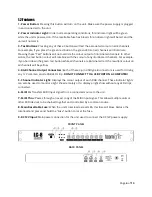
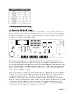
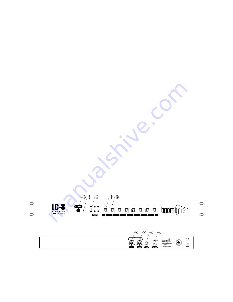
1.2 Features 

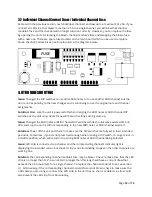
1 - Power Button:

 Pressing this button will turn on the unit. Make sure the power supply is plugged 

in and connected to the unit. 

2 - Power Indicator Light:

 Under normal operating conditions, this indicator light will be green 

while the unit is powered on. If the resettable fuse has blown, this indicator light will be red and the 
unit will not work. 

3 - Test Buttons:

 Pressing any of these 3 buttons will test the associated colour on all 8 channels. 

For example, if you press the green test button, the green LEDs on all channels will illuminate. 
Pressing these 

Test

 buttons will not override the colour output of illuminated channels. In other 

words, the test button colour will combine with the colour of any illuminated channels. For example, 
if you hold down the green test button while all channels are illuminated red, the resultant colour on 
all channels will be yellow. 

4 - RGB Channel Output Connectors:

 Each of these 4-pin USB type B connectors is used for driving 

any 12V common anode RGB LED strip. 

DO NOT CONNECT TO A USB PORT ON A COMPUTER!


5 - Channel Indicator Light:

 Displays the colour output of each RGB channel. These indicator lights 

can also be used to monitor a light show remotely or to display a light show without any LED strips 
connected. 

6 - MIDI In:

 Transfers MIDI input signal from a connected source to the unit. 

7 - MIDI Thru: 

Passes through an exact copy of the MIDI input signal. This allows multiple units or 

other MIDI devices to be chained together and controlled by a common source. 

8 - Main Resettable Fuse:

 When the 

unit’s total load

 exceeds 8A, this fuse will blow. Reduce the 

total load and press and hold the 

Fuse

 button to reset the fuse. 

9 - DC12V Input:

 Main power connection for the unit used to connect the DC12V power supply.


FRONT PANEL 


BACK PANEL


Содержание LC-8

Страница 1: ...Page 1 of 13 LC 8 8 CH LIGHTING CONTROLLER USER MANUAL BOOMLIGHTS 265 McNeilly Road Stoney Creek ON L8E 5H2 Canada 2021 BOOMLIGHTS All rights reserved ...

Страница 2: ...e Default Settings 6 2 3 1 Changing the MIDI Note DIP Switches 6 2 3 2 MIDI Note DIP Switch Table 7 2 3 3 Changing the MIDI Channel DIP Switches 9 2 3 4 MIDI Channel DIP Switch Table 10 2 4 Linking Multiple Units Together 10 3 0 CURRENT LIMITS 11 3 1 Total Current Draw Main Resettable Fuse 11 3 2 Individual Channel Current Draw Individual Channel Fuse 12 4 0 TROUBLESHOOTING 12 5 0 SPECIFICATIONS 1...

Страница 3: ...roller that has been specially designed by musicians for musicians Treat your lighting like an instrument by using MIDI to create custom automated light shows No additional hardware or software required The LC 8 seamlessly integrates with any existing hardware or software set up Just plug and play to begin elevating your performances with synchronized lighting The LC 8 is controlled using 8 groups...

Страница 4: ...utton while all channels are illuminated red the resultant colour on all channels will be yellow 4 RGB Channel Output Connectors Each of these 4 pin USB type B connectors is used for driving any 12V common anode RGB LED strip DO NOT CONNECT TO A USB PORT ON A COMPUTER 5 Channel Indicator Light Displays the colour output of each RGB channel These indicator lights can also be used to monitor a light...

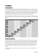
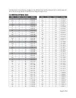
Страница 5: ... A 1 NOTE 22 R CH 8 A 1 NOTE 21 G G 1 NOTE 20 B G 1 NOTE 19 R CH 7 F 1 NOTE 18 G F 1 NOTE 17 B E 1 NOTE 16 R CH 6 D 1 NOTE 15 G D 1 NOTE 14 B C 1 NOTE 13 R CH 5 C 1 NOTE 12 G B 2 NOTE 11 B A 2 NOTE 10 R CH 4 A 2 NOTE 9 G G 2 NOTE 8 B G 2 NOTE 7 R CH 3 F 2 NOTE 6 G F 2 NOTE 5 B E 2 NOTE 4 R CH 2 D 2 NOTE 3 G D 2 NOTE 2 B C 2 NOTE 1 R CH 1 C 2 NOTE 0 G 2 2 Colour Combinations You can create an array...

Страница 6: ...down position means that this particular module s channel will respond to MIDI notes 0 1 and 2 which will be green red and blue respectively If you refer to the table in section 2 3 2 you can see the default DIP switch settings which are highlighted in grey To set the DIP switches correctly to the desired MIDI note refer to the Binary column on the table in section 2 3 2 These 7 number sequences r...

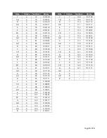
Страница 7: ...010 A 1 46 0101110 B 2 11 0001011 B 1 47 0101111 C 1 12 0001100 C 2 48 0110000 C 1 13 0001101 C 2 49 0110001 D 1 14 0001110 D 2 50 0110010 D 1 15 0001111 D 2 51 0110011 E 1 16 0010000 E 2 52 0110100 F 1 17 0010001 F 2 53 0110101 F 1 18 0010010 F 2 54 0110110 G 1 19 0010011 G 2 55 0110111 G 1 20 0010100 G 2 56 0111000 A 1 21 0010101 A 2 57 0111001 A 1 22 0010110 A 2 58 0111010 B 1 23 0010111 B 2 59...

Страница 8: ...1 A 4 82 1010010 A 7 118 1110110 B 4 83 1010011 B 7 119 1110111 C 5 84 1010100 C 8 120 1111000 C 5 85 1010101 C 8 121 1111001 D 5 86 1010110 D 8 122 1111010 D 5 87 1010111 D 8 123 1111011 E 5 88 1011000 E 8 124 1111100 F 5 89 1011001 F 8 125 1111101 F 5 90 1011010 F 8 126 1111110 G 5 91 1011011 G 8 127 1111111 G 5 92 1011100 G 8 A 5 93 1011101 A 8 A 5 94 1011110 A 8 B 5 95 1011111 B 8 C 6 96 11000...

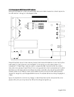
Страница 9: ...e used to configure the MIDI channel in which the unit will respond to For example if only DIP switch 4 is in the up position on the main board while the other switches are in the down position resulting in the binary code 0001 the unit will respond to MIDI channel 2 Refer to the Binary column on the table in section 2 3 4 for the DIP switch positions required to change the unit s designated MIDI ...

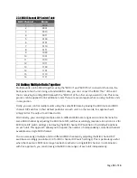
Страница 10: ...IP switches in their default positions on each unit In other words this approach will simply mirror the output to all linked units Alternatively you can assign multiple units to different MIDI note ranges and control them via the same MIDI channel by adjusting the MIDI note DIP switches accordingly see table in section 2 3 2 for MIDI note DIP switch settings but leaving the MIDI channel DIP switch...

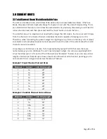
Страница 11: ...t for a lighting set up there are two key current values to consider each individual channel cannot exceed 2 5A and the sum of the current draw from all 8 channels cannot exceed 8A On average our LED strips consume 1A for approximately every 40 With that said there are numerous ways you can distribute the unit s overall power budget You can use equal length LED strips that draw up to 1A for each o...

Страница 12: ...Issue Changed the MIDI notes or MIDI channel DIP switches while the unit was powered off but after start up the unit is still not responding to the new MIDI notes or MIDI channel selected Solution Power off the unit and check to make sure the DIP switches are fully set in their intended positions Sometimes if you do not press hard enough when moving a DIP switch it can get stuck in a middle positi...

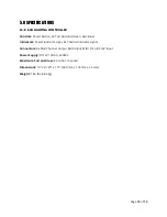
Страница 13: ...uttons Green Red Blue Indicators Power Indicator Light 8x Channel Indicator Lights Connectors 8x RGB Channel Output MIDI Input MIDI Thru DC12V Input Power Supply DC12V 10A 90 240VAC Maximum Current Draw 8A 2 5A channel Dimensions 19 x 4 125 x 1 75 483 mm x 105 mm x 45 mm Weight 1 86 lbs 0 84 kg ...

Отзывы: