Doc.# 985001
07/21/00
On modules so equipped, the "Test" button is located on the module's control/display front panel. For
modules without a control/display front panel, a normally-open momentary switch should be installed to
serve as a test switch for this procedure. Refer to applicable field wiring diagrams for switch connection
points.
3) Read the DC bus meter and subtract the "Boost" voltage.
When the "Test" button is pushed, the "Threshold" voltage level is "Boosted" for a period of approximately 2
seconds. During this "Boost" period, you should see the DC bus level increase. The amount that the DC Bus
actually increases will depend on the Boost and Threshold level adjustments as well as the input voltage and
DC bus output current.
For example, for a Ride-Thru system with an input voltage of 460VAC, the "Threshold" voltage level is
preset to be 590VDC and the "Boost" voltage level is factory preset for an increase of 100VDC.
Assuming that these preset levels have not been altered, initiating the test described above on a lightly loaded
system of this nature would cause the DC bus level to rise to 690VDC ( 100VDC). Subtracting the
"Boost" voltage (100VDC) from this reading shows that the actual "Threshold" voltage level is 590VDC.
Initiating this test on a heavily loaded system of this nature would also cause the DC bus level to rise.
However, the DC bus would stop rising once current limit is reached.
NOTE:
The "Boost" voltage level is adjustable and is factory preset. It is not recommended that this setpoint
be altered. If this setpoint has been changed from its original factory setting, this test method will not be
accurate.
2.2 Method 2: Determining The Threshold Voltage Setpoint For An Off-Line And
Unloaded System
1) Remove input voltage supply from system.
Disconnect the input voltage to the Ride-Thru while monitoring the DC bus voltage. As the DC bus drops to
the "Threshold" setpoint voltage, the Ride-Thru module will become active. The Ride-Thru will then
maintain the DC bus voltage at the "Threshold" setpoint level for approximately 1 second while the primary
capacitor discharges, at which point, the DC bus will continue to drop. Read the DC bus voltage as it is being
maintained. This is the "Threshold" setpoint voltage.
3. Adjust The Setpoints And Repeat The Test
Once the actual "Threshold" voltage has been determined you can make adjustments, if required, to achieve
the optimum setting for your system. The "Low DC Bus" setpoint should be adjusted to match any
"Threshold" adjustment that is made.
The "Threshold" voltage should be set to approximately 10% below the nominal DC bus under load, and
coordinated to be above the associated inverter's under-voltage trip level. Most inverters have an under-
voltage trip point of approximately 15% below the nominal DC bus under load. Some inverters can be
reprogrammed to change this trip level as needed.
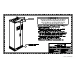
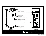
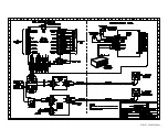
Adjustment pot R7 on the 3460C1 control board (see fig.1) is used to set the "Threshold" voltage level.
Adjusting the pot in a clockwise direction will raise the setpoint level by approximately 5.5 volts per
revolution of the pot adjustment screw. Alternately, a counter-clockwise adjustment of the pot will lower the
setpoint level. The "Threshold" setpoint level can be adjusted to approximately
±
35VDC of the factory
setpoint listed in Table-1.
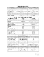
Adjustment pot R3 on the 3460D4 power supply board (see fig.2) is used to set the "Low DC Bus" voltage
level. Adjusting the pot in a clockwise direction will raise the setpoint level by approximately 5.5 volts per
revolution of the pot adjustment screw. Alternately, a counter-clockwise adjustment of the pot will lower the
setpoint level. Be sure to match any adjustment made to the "Threshold" voltage level.
After making the adjustments, repeat the test from Section 2 to verify the new setpoint. Fine tune the
adjustment and retest as necessary.
Содержание M3460R
Страница 11: ...990078_19990803 doc ...
Страница 22: ...970066P_19991230 doc ...
Страница 23: ...980265P_19991230 doc ...
Страница 25: ...990256_19991022 doc ...
Страница 27: ...000122_20000425 doc ...
Страница 29: ...990036_19990827 doc ...
Страница 30: ...970104_19991025 doc ...
Страница 31: ...970103_19981028 doc ...
Страница 32: ...990026_19991021 doc ...
Страница 33: ...990243_20000712 doc IGBT 150A 1200V IGBT 150A 1200V 150A 1200V IGBT 150A 1200V IGBT ...
Страница 34: ...990244_20000712 doc ...
Страница 35: ...980233_20000725 doc ...
Страница 36: ...970200_20000718 doc ...
Страница 37: ... SYSTEM NOTES ...

