background image


 Doc.# 985001 

  07/21/00


“THRESHOLD VOLTAGE” AND “LOW BUS SENSE” 

ADJUSTMENT PROCEDURES FOR  

MODEL M3460 RIDE-THRU MODULES 

1. Overview 

The "Threshold" voltage level is the voltage at which the Bonitron Model M3460 Ride-Thru module 
maintains the DC bus during a power dip. Whenever the DC bus level drops to the "Threshold" setpoint, the 
Ride-Thru module becomes active to regulate the DC bus voltage to the "Threshold" setpoint voltage. 

The "Threshold" level is factory preset on all Bonitron Model M3460 Ride-Thru modules. These levels are 
specified in the General Specifications section of the Customer Reference manual for each Ride-Thru 
module. However, some field adjustment of this level may be required to achieve the optimum setpoint level 
for any given system.  

It is important to note that the Ride-Thru module’s "Low DC Bus" or "Output Under Voltage (OUV)" 
setpoint is factory preset to 25V below the "Threshold" voltage. This setpoint should be maintained at 25V 
below Threshold to avoid improper OUV fault activity.  

Table-1 below lists the typical factory setpoints for the "Threshold", "Low DC Bus (OUV)" and "Test Boost" 
levels for the Model M3460 Ride-Thru modules based on the system AC or DC input voltage requirements. 
Be sure to check the Customer Reference manual for each Ride-Thru module for specific setpoint levels.


Table-1: Factory Setpoints for Threshold and Test Boost Voltages 

INPUT VOLTAGE 

THRESHOLD 

LOW DC BUS (OUV) 

TEST BOOST 

230VAC 

290VDC 

265VDC 

+50VDC 

370VDC 

490VDC 

465VDC 

+75VDC 

380VAC 

490VDC 

465VDC 

+75VDC 

400VAC 

505VDC 

480VDC 

+100VDC 

400VDC 

595VDC 

570VDC 

+100VDC 

415VAC 

520VDC 

495VDC 

+100VDC 

460VAC 

590VDC 

565VDC 

+100VDC 

2. Determining The Threshold Voltage Setpoint 

Testing and adjustment of the "Threshold" voltage setpoint can be performed on systems in either an "On-line 
and loaded" or an "Off-line and unloaded condition as described in methods 1 and 2 below. Each of the two 
methods described require that you monitor the DC bus voltage during the testing and adjustment procedures. 

Be sure to read through both adjustment methods completely before attempting any adjustment of the 
"Threshold" and "Low DC Bus" voltage setpoints. 

2.1 Method 1: Determining The Threshold Voltage Setpoint For An On-Line And 

Loaded System 

1) Verify proper installation. 

Ensure that the Bonitron Model M3460 Ride-Thru module has been properly installed and wired according to 
all applicable system and module wiring diagrams. 

2) Push the "Test" button. 

Push the "Test" button while monitoring the DC bus voltage.  

Содержание M3460R

Страница 1: ...ROUND COURT NASHVILLE TENNESSEE 37211 615 244 2825 FAX 615 244 2833 M3460R 4CAB1 150A2 A4 460VAC 150KW Ride Thru Cabinet System with PLC Interface and Metering Single or Dual Totalizers Customer Reference Manual ...

Страница 2: ...nsional Outline and Layout Drawing 980265P 12 30 99 22 Ride Thru Rack Disconnect Panel Layout 990255 10 22 99 23 Typical R1 Chassis Ride Thru Module With Metering and PLC Interface Dimensional Outline 990256 10 22 99 24 Typical Ride Thru Cabinet Customer Connections and Internal Component ID Drawing 000199 07 12 00 25 Basic Ride Thru and Inverter Power Interconnection 000122 04 25 00 26 Example of...

Страница 3: ...le with a 2 second 2X surge capability The Ride Thru module is designed to operate continuously 24 hours per day 365 days per year 2 Specifications GENERAL SPECIFICATIONS PARAMETER SPECIFICATION Input AC Line Voltage 460VAC 10 3 phase 50 60 Hz Output DC Bus Voltage 640VDC nominal 590VDC minimum Inactive Power Consumption 100 Watts Ride Thru Requirement 50 dip of all 3 phases Duration 120 cycles 2 ...

Страница 4: ...n A4 display panel only Counter 0 999999999 Test System LED On Off Power LED On Off Precharge Complete PCC LED On Off Ride Thru Ready RTR LED On Off Ride Thru Active RTA LED On Off AC Voltage Dip LED On Off Heatsink Over Temperature LED On Off INPUT OUTPUT SIGNALS STATUS SIGNAL OUTPUT TYPE ACTIVE STATE Precharge Complete Isolated Open Collector Transistor On Ride Thru Ready Isolated Open Collector...

Страница 5: ...IGBT chopper circuit for each stage of the Ride Thru module Each chopper circuit includes 1 DC bus inductor 1 current sensor and 1 IGBT chopper transistor If the DC bus level drops the IGBT chopper transistor is turned on and the DC bus inductor is connected between the primary DC bus and the negative bus The inductor current increases and energy is stored in the inductor until a maximum current i...

Страница 6: ...e 4460D1 display board mounted on the back of the display panel 3 2 4 Active Cycles Counter Reset Push button The Active Cycles Counter Reset push button will cause the Active Cycles Counter to be reset to zero 3 2 5 Total RTA Cycles Counter option A4 display panels only The Total RTA Cycles Counter indicates the lifetime total number of times the Ride Thru module has been active Tests initiated b...

Страница 7: ...g and doc 993004 Recommended Input Power Wiring Sizes And Power Source Fusing For Model M3460R Cabinet Mounted Ride Thru Systems for additional information pertaining to this section Customer power wiring connections to the 3 phase AC line and DC bus are provided at the upper left of the rack back panel The 3 phase AC and DC bus breakers are mechanically interconnected and are operated by the door...

Страница 8: ...ch will be OFF if the AC line dips below the AC voltage dip setpoint or if any single phase is missing The connections are located on terminals 13 and 14 of 4460C1 connector TS2 This signal is also provided to the 3460M1 Fault Multiplex board see 3 4 7 3 4 6 Temperature Sensor Output The temperature sensor output is an isolated open collector transistor output which will be OFF when the backplate ...

Страница 9: ...1 C2 Q1 L1 D1 Vout If the input voltage dips the output voltage would tend to follow the input at the same ratio A drop in the output voltage is sensed in the Ride Thru control circuitry and transistor Q1 is turned on The D1 diode is then in a blocking mode and the current in inductor L1 starts to increase due to the conduction of transistor Q1 The current in L1 starts increasing at the rate of Vi...

Страница 10: ...upplied to the load while some of the inductors are recharging This process results in a much smoother primary and secondary load current and can be expanded to as many stages as needed to reach a required KW rating The reason that paralleling is feasible is because each parallel circuit acts as a current source entering the Vout node voltage An easy concept to grasp is that of a multiple cylinder...

Страница 11: ...990078_19990803 doc ...

Страница 12: ...priate Bonitron Customer Connections Component ID drawing and Rack Disconnect Panel Layout drawings for connection points 5 Ensure all terminal safety covers are installed over AC and DC terminals 6 Connect shunt trip wiring to the Bonitron Ride Thru disconnect panel Refer to Bonitron Example Of Shunt Trip Coil Wiring drawing 990009 for connection Use appropriate Bonitron Customer Connections Comp...

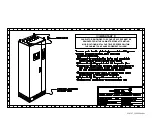
Страница 13: ...0163_19990804 doc REMOVED FROM THE CABINET BEFORE ATTEMPTING PANELS TO BE MODIFIED FOR CONDUIT ACCESS MUST BE MODIFICATIONS METAL PARTICLES DROPPED WITHIN THE CABINET CAN CAUSE EQUIPMENT FAILURE IMPORTANT ...

Страница 14: ...s Field Connections Layout drawing 000205 Please note that the input power source and power wiring supplied to the M3460R Ride Thru system must be capable of providing a 2 second surge at twice the rated power of the Ride Thru system Steady state CLASS J TIME DELAY or equivalent power source fusing should be used to support the requirement for 2 second surge capability at twice the rating of the R...

Страница 15: ...stment of the under voltage trip setting Refer to Bonitron Threshold Voltage Adjustment Procedure document 985001 for details on how the Ride Thru DC bus threshold can be changed 3 With the Ride Thru disconnect turned off apply power to the system Ensure that the associated inverter is working properly Confirm the under voltage trip point if possible 4 Turn on the Ride Thru disconnect switch and o...

Страница 16: ...off the Bonitron Ride Thru disconnect and watch the DC bus voltage fall See threshold adjustment procedure AC VOLTAGE DIP LED comes ON immediately RIDE THRU ACTIVE LED will come ON when the bus drops to the threshold The DC bus will hold at the threshold momentarily Allow the DC bus to discharge until the PRECHARGE COMPLETE LED goes OFF Repeat step 4 9 Verify system capability Turn on the Bonitron...

Страница 17: ...modules based on the system AC or DC input voltage requirements Be sure to check the Customer Reference manual for each Ride Thru module for specific setpoint levels Table 1 Factory Setpoints for Threshold and Test Boost Voltages INPUT VOLTAGE THRESHOLD LOW DC BUS OUV TEST BOOST 230VAC 290VDC 265VDC 50VDC 370VDC 490VDC 465VDC 75VDC 380VAC 490VDC 465VDC 75VDC 400VAC 505VDC 480VDC 100VDC 400VDC 595V...

Страница 18: ... monitoring the DC bus voltage As the DC bus drops to the Threshold setpoint voltage the Ride Thru module will become active The Ride Thru will then maintain the DC bus voltage at the Threshold setpoint level for approximately 1 second while the primary capacitor discharges at which point the DC bus will continue to drop Read the DC bus voltage as it is being maintained This is the Threshold setpo...

Страница 19: ...0C1B RIDE THRU CONTROL BOARD FREQUENCY T 0 R7 R15 IC4 IC3 IC1 IC10 I I IC14 READY R T ACTIVE R T CHOPPER CLOCK K2 K1 IC2 IC12 IC11 IC7 IC8 IC9 IC6 IC5 IC13 R2 THRESHOLD J1 CIRCUIT COMMON TB1 TB2 TB3 TB4 THRESHOLD ADJUSTMENT POT R7 Fig 2 Ride Thru Module 3460D4 Power Supply Board Layout SENSE DC BUS INPUT 3 N C LOW BUS 1 DIP 1 3 GND VOLTAGE ADJ 20V 1 COM 20V 20V ISO N C 6 R3 TB1 TM2 Q7 S1 U1 C5 TM1...

Страница 20: ...r Verify applicable steps of the start up procedure 8 Press the TEST SYSTEM button on the front panel of the Ride Thru The RIDE THRU ACTIVE LED flashes on The BUS VOLTAGE meter rises This proves the stage is operational 9 Remove power from Bonitron Ride Thru and allow DC bus voltage to drain at least until RIDE THRU READY and PRECHARGE COMPLETE LEDs go out 10 Open Ride Thru cabinet door to access ...

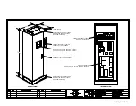
Страница 21: ...5 CB2 LINE STATUS DISPLAY PANEL REMOVABLE COVER PANEL CAN BE MODIFIED FOR CONDUIT ACCESS DOOR MECHANISM INTERLOCKED WITH DISCONNECT ACTUATOR FOR SAFETY FOR BOTH AC AND DC POWER SINGLE DISCONNECT ACTUATOR MODIFIED FOR CONDUIT ACCESS REMOVABLE PLINTH SIDES CAN BE LIFTING EYES 4 SEE DRAWING 990163 FOR OPTION A2 PANEL SEE DWG 970066P FOR OPTION A4 PANEL SEE DWG 980265P SEE DRAWING 990163 CABINET DISCO...

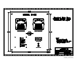
Страница 22: ...970066P_19991230 doc ...

Страница 23: ...980265P_19991230 doc ...

Страница 24: ...990255_19991022 doc TB1 TB2 C NO NC N A N H 120VAC AUX CONTACT SHUNT COIL 6 4 5 3 2 1 CB2 CB1 LINE LOAD LOAD LINE 3O AC LINE DC BUS L2 L1 L3 5 4 3 2 1 TYPICAL RACK DISCONNECT PANEL LAYOUT GND ...

Страница 25: ...990256_19991022 doc ...

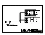
Страница 26: ...DE THRU PRECHARGE RUN IN 6 7 8 10 9 11 TOP OF RACK CB1 CB2 F4 D4 D5 F5 D3 V2 V1 V3 F3 LOAD LINE LINE LOAD TB2 NO C NC 6 4 5 AUX CONTACT N H N A 2 3 1 SHUNT COIL 120VAC SHUNT COIL 120V HOT SHUNT COIL 120V NEUT NOT USED AUX CONTACT C AUX CONTACT N O AUX CONTACT N C REFER TO DOCUMENT 993004 FOR IMPORTANT FIELD POWER WIRING NOTES INPUT POWER WIRING SIZES AND SOURCE FUSING SELECTION INFORMATION D1 D2 F...

Страница 27: ...000122_20000425 doc ...

Страница 28: ...ET WHEN THE SHUNT TRIP COIL IS IS DE ENERGIZED CONNECTING 115VAC ACROSS THE SHUNT TRIP COIL CONNECT SUCH THAT WHEN THE INVERTER IS SWITCHED OFF THE RELAY 3460 RIDE THRU CABINET GENERIC SHUNT TRIP COIL WIRING OFF ON MAIN POWER CONTACT AUX DC BUS AC LINE DISCONNECT ENERGIZED ALL RIDE THRU POWER IS DISCONNECTED CABINET NEUTRAL HOT ...

Страница 29: ...990036_19990827 doc ...

Страница 30: ...970104_19991025 doc ...

Страница 31: ...970103_19981028 doc ...

Страница 32: ...990026_19991021 doc ...

Страница 33: ...990243_20000712 doc IGBT 150A 1200V IGBT 150A 1200V 150A 1200V IGBT 150A 1200V IGBT ...

Страница 34: ...990244_20000712 doc ...

Страница 35: ...980233_20000725 doc ...

Страница 36: ...970200_20000718 doc ...

Страница 37: ... SYSTEM NOTES ...

Отзывы: