


12
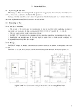
2.2.4
Wiring the Unit
Figure 2.2.5 shows the general schematic for wiring the unit.
Notes
:
1. The kinds of actuating devices being connected to the outputs are defined by user and can differ from the
ones specified above.
2. Load connection modules (MPN) shall be installed inside the actuating appliances (except for starting
circuits of fixed fire extinguishing systems).
3. In case of connecting starting circuits of fire-fighting systems or equipment in explosion protected housing,
load connection modules can be installed in close vicinity from them.
4. If an output is not in use, one can replace load connection module with a 510 Ohm – 1/2W resistor.
Figure 2.2.5.
General Schematic for Connecting the Unit
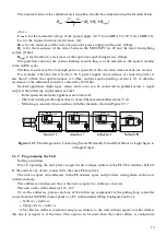
Connecting to fixed fire-fighting systems should be conducted in accordance with the schematic
in Figure 2.2.6. The length of wires used to connect a fire-fighting systems and the resistance of the
additional resistance shall be such that the required squib activation current will be provided.
Figure 2.2.6.
Preferable Diagram for Connecting a Discharge Circuit


