background image

2-Channel Audio Power Amplifier


Configuration Guide

NQ-A2060-G2, NQ-A2120-G2, NQ-A2300-G2

© 2021 Bogen Communications, Inc.

All rights reserved.

740-00159

210811


Содержание NQ-A2300-G2

Страница 1: ...2 Channel Audio Power Amplifier Configuration Guide NQ A2060 G2 NQ A2120 G2 NQ A2300 G2 2021 Bogen Communications Inc All rights reserved 740 00159 210811 ...

Страница 2: ...rs 9 Standalone Operation Configuration Settings 11 Accessing Log Files 15 Setting DSP Parameters 17 Setting the Channel Level 21 Signal LEDs Clip LED and VU Meters 21 Muting a Channel 21 Adjusting Volume Levels 22 Knob Adjustments 22 Amplifier Mute 22 Compressor 24 Delay 26 Graphic EQ 28 High Low Pass 29 Limiter 31 Noise Gate 33 Parametric EQ 35 Peak Limiter 36 Presets 38 RMS Limiter 41 Router 43...

Страница 3: ...ngs 23 Figure 10 Compressor Settings 24 Figure 11 Delay Settings 27 Figure 12 Graphic EQ Settings 28 Figure 13 High Low Pass Parameters 29 Figure 14 Limiter Settings 32 Figure 15 Noise Gate Settings 34 Figure 16 Parametric Equalizer Settings 35 Figure 17 Peak Limiter Settings 37 Figure 18 Presets Settings 39 Figure 19 RMS Limiter Settings 41 Figure 20 Router 43 Figure 21 Settings Parameters for 2 ...

Страница 4: ...one enabled 12 Table 7 Logs 16 Table 8 DSP Page 19 Table 9 DSP Features 20 Table 10 Amplifier Mute Settings 23 Table 11 Compressor Settings 25 Table 12 Delay Settings 27 Table 13 High Low Pass Parameters 30 Table 14 Limiter Settings 33 Table 15 Noise Gate Settings 34 Table 16 Peak Limiter Settings 38 Table 17 Preset Settings 40 Table 18 RMS Limiter Settings 42 Table 19 Signal Present Parameters 47...

Страница 5: ... 10 seconds the appliance returns to the factory default configuration settings Returning to the default configuration settings does not change the appliance s firmware The following sections describe settings and configurations that can be applied to this device which are not controlled by the Nyquist server For information about using Nyquist s automatic configuration process refer to the approp...

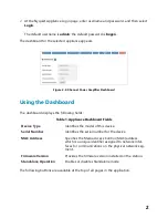
Страница 6: ...all pages in the application Figure 2 2 Channel Power Amplifier Dashboard Table 1 Appliance Dashboard Fields Device Type Identifies the model of this device Serial Number Identifies the serial number for the device MAC Address Specifies the Media Access Control MAC address which is a unique identifier assigned to network inter faces for communications on the physical network seg ment Firmware Vers...

Страница 7: ...ays the dashboard Configuration Settings Accesses the Configuration Settings page where you can view and set various options If Standalone Opera tion is not enabled you can also receive configuration settings from a Nyquist server Network Settings Accesses the Network Settings page where you can view and set network settings such as the static IP address Firmware Update Accesses the Firmware Updat...

Страница 8: ...on checks the Bogen website for the latest firmware version available If a version newer than the one currently installed is found it is downloaded to the appliance 3 Alternatively if you already have a firmware file you would like to install to the appli ance select Upload Firmware to upload the firmware file from your computer to the Note A Nyquist appliance connected to the Nyquist network rece...

Страница 9: ...d though not installed onto the appliance Update Firmware Available only when a new firmware version has been loaded onto the appliance as specified in New Nyquist Version Installs the loaded firmware A reboot may be required after installation Upload Firmware Prompts the user to specify a firmware file which will then be loaded though not installed onto the appliance Note To obtain the firmware f...

Страница 10: ...yquist server or manually by using the appliance s web UI To manually configure network settings 1 On the appliance web UI s main page select Network Settings 2 Select your desired network settings 3 Select Save Network settings are described in the following table Figure 4 Network Settings ...

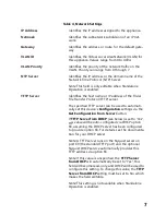
Страница 11: ...rver The specified TFTP server can be used to automati cally set this device s Configuration settings via the Get Configuration from Server button If TFTP Server from DHCP see below is set to Yes this value will be auto configured via DHCP option 66 assuming the DHCP server has been configured to provide option 66 For details see the documenta tion for your DHCP server Note A TFTP server runs on t...

Страница 12: ...option 66 value and use the manually configured value of the TFTP Server see above Note This setting is not available when Standalone Operation is enabled DHCP Enabled Indicates if the device is enabled to use DHCP to retrieve its IP configuration Reboot Appliance Indicates that this appliance should reboot when the Save button is clicked Table 4 Network Settings Continued ...

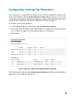
Страница 13: ...Standalone Operation Configuration Settings on page 11 To configure your Nyquist appliance 1 On the appliance Web UI s main page select Configuration Settings 2 Select your desired settings as described in Table 5 on page 10 for normal configura tion or Table 6 on page 12 for Standalone Operation configuration 3 Select Save The following table describes the Configuration Settings tab settings when...

Страница 14: ...ages All Call Identifies the IP address port number cut level vol ume and station list used for all call pages Audio Distribution Identifies the IP address port number cut level vol ume and station list used for audio distribution Multicast Identifies the IP address port number cut level vol ume and station list used for the multicast audio stream of one or more zones Port Number Shows the output ...

Страница 15: ...Operation Configuration Settings The following table describes the Configuration Settings tab settings when Standalone Operation is enabled for this device Figure 6 Appliance Configuration Settings Standalone enabled ...

Страница 16: ...nnel A B Output Power Controls the output power to the speaker This can be a value from 6 to 6 dB Enable SIP Calls Enables this device to receive one way SIP calls wherein only the caller can be heard such as announcements If enabled a number of SIP related configuration settings are displayed Yes or No SIP Server Addressa Specify the IP address of the SIP Registration Server with which the device...

Страница 17: ...Channel A or B This can be a value from 42 and 0 dB The default value is 20 dB Note To modify click on the value adjust the slider on the popup using the cursor keys or mouse and click the check box button a Available only when Enable SIP Calls has a value of Yes Multicast IP Address Specifies the multicast IP address on which to receive audio streams Multicast Port Number Specifies the multicast ...

Страница 18: ... codec operating at 48 56 and 64 kbps OPUS Music quality An audio codec format designed for speech and general audio supporting low latency constant and variable bitrate encoding 6 to 510 kbps and five sampling rates from 8 to 48 kHz Channels Channel s on which the audio streams will be output One or both of the following values Channel A Channel B Cut Level dB Specifies the cut level for the audi...

Страница 19: ...2 From the drop down menu select the log that you want to view Multiple versions of the same log and zipped copies of the log may be available 3 To export the file select Export A link to a txt file appears in the browser s lower left corner Note Multicast Addresses should be ordered by priority highest priority first If multi ple streams are active on the same channel simultaneously the one with ...

Страница 20: ...information at the time of event auth log Contains system authorization information including user logins and authentication methods that were used btmp Contains information about failed login attempts daemon log Contains information logged by the various back ground daemons that run on the system debug Contains errors and debug information dpkg log Contains information that is logged when a packa...

Страница 21: ...ixer s two output channels A and B via the DSP Router where it can be conditioned using the mixing board interface Digital VoIP audio streams received over the network whether as SIP initiated phone calls or as multicast audio see SIP and Multicast configuration settings in Configuration Settings Tab Parameters on page 9 are also controlled by the mixer s output channels A and B kern log Contains ...

Страница 22: ...used as an Audio Distribution source the signals can be distributed as digital audio over the network using a Nyquist server s Audio Distribution feature Note Audio Distribution functionality is not supported in Standalone Operation mode From the DSP page you can view and control the signal levels for each channel Selecting the DSP Features button for a channel displays a list of DSP features whic...

Страница 23: ...estored when the new device is swapped for the old on the Nyquist server Note This button appears on each DSP feature page Mute Silences the audio for the selected channel DSP Features button Presents a menu of DSP features that can be applied to the corresponding channel Level Slider Adjusts the channel volume level in 1 dB increments NET IN LED Illuminates when a signal is being received from th...

Страница 24: ...ic EQ Uses a center primary frequency to allow tailoring of the frequency content of an audio signal Peak Limiter Limits the signal to a specified threshold based on the sig nal s instantaneous levels Presets Provides predefined configurations of DSP features tai lored for specific speakers models RMS Limiter Limits the signal to a specified threshold based on the sig nal s average levels over tim...

Страница 25: ...N VU meter indicates the strength of the channel s input signal after gain adjust ments while the OUT VU meter indicates the strength of the channel s output signal The VU meter not only illuminates green yellow or red depending on the signal level but also has a scale ranging from 60 to 0 dB to indicate the actual signal level Muting a Channel You can mute a channel to cut off an audio signal and...

Страница 26: ... one or more settings The value of a knob can be adjusted in one of two ways 1 Click the knob control hold the mouse button down and drag the mouse up or down to increase or decrease the value 2 Double click the knob type a value into the resulting popup and click the Save but ton Amplifier Mute The Amplifier Mute feature disables the output signal when the input signal registers below a specified...

Страница 27: ...hannel 3 From the drop down menu select Amplifier Mute 4 Adjust the following settings as needed Figure 9 Amplifier Mute Settings Note If you want to return to the factory settings select the Reset icon that appears in the right corner Table 10 Amplifier Mute Settings Enable Enables or disables the amplifier mute effect for this chan nel ...

Страница 28: ...t Compressor 4 Make desired adjustments using the controls described in Table 11 Compressor Set tings on page 25 Threshold Sets the minimum threshold level that the signal must reach to allow the signal to be sent to the output channel Threshold range is 135 to 21 dB Status Indicates if channels A B are in Amplifier Mute mode On or not Off Figure 10 Compressor Settings Note If you want to return t...

Страница 29: ...is 1 to 500 ms Decay Sets how quickly or slowly compression will be removed from the signal after the signal has dropped below the threshold and the Hold interval has expired It specifies the length of time over which the compression ratio will gradually decrease from full compression to no com pression The range is 0 to 2000 ms Knee Sets how far below the threshold compression will begin to be gr...

Страница 30: ...ion ratio to be applied to the signal For example if the ratio is set for 6 6 1 the input signal must increase by 6 dB for the output level to increase by 1 dB The range is 1 to 100 Input meter Shows the strength of the input signal Output meter Shows the strength of the output signal providing a visual indicator of the effect of the compressor on the output signal Comp LED Illuminates when compre...

Страница 31: ...s using the controls described in Table 12 Delay Settings on page 27 Figure 11 Delay Settings Note If you want to return to the factory settings select the Reset icon that appears in the right corner Table 12 Delay Settings Delay ms Sets the number of milliseconds by which the input signal will be delayed before sending it to the output channel Signal LED Illuminates when the input signal is prese...

Страница 32: ...nd 12 dB The frequency of each slider is different and range from 25 Hz to 20 000 20k Hz By default each knob is set at 0 dB which means that no frequencies are being boosted or cut 4 Adjust frequencies as desired ensuring the Enable LEDs are green for the selected frequencies Clip LED Illuminates when the input signal is clipping Input meter Indicates the strength of the input signal Figure 12 Gr...

Страница 33: ...ne exclusively for vocals which can be very useful in a noisy environment to filter out the higher and lower frequencies that could mask the human vocal range during announce ments You can specify the range of frequencies that will pass through the high pass and low pass filters and select the type of filter that is used through the channel s High Low Pass drop down menu option To adjust the high ...

Страница 34: ...e frequency by moving the knob click and move up or down or by dou ble clicking the knob and typing the frequency When typ ing the frequency only numeric values from 20 Hz to 20 000 Hz can be entered The high pass filter attenuates content below this fre quency and lets frequencies above this cutoff frequency pass through the filter Type Available filter types are Linkwitz Riley 12 24 36 and 48 dB...

Страница 35: ...king the knob and typing the frequency When typ ing the frequency only numeric values from 20 Hz to 20 000 Hz can be entered The low pass filter attenuates content above this fre quency and lets frequencies below this cutoff frequency pass through the filter Type Available filter types are Linkwitz Riley 12 24 36 and 48 dB per octave Butterworth 6 12 18 24 30 36 42 and 48 dB per octave Bessel 12 1...

Страница 36: ... 6 Select the Menu button for the channel or select the Menu button for the Output 7 From the drop down menu select Limiter 8 Adjust the following settings as needed Figure 14 Limiter Settings Note If you want to return to the factory settings select the Reset icon that appears in the right corner ...

Страница 37: ...hold Sets the signal level at which the limiter is triggered Any signal exceeding this threshold will be compressed to this level The range is 24 to 24 dB Decay Sets the rate for turn off of the limiter after the signal is below the threshold Decay range is 5 to 2300 milliseconds RMSTC Root Mean Square Time Constant Sets how fast the limiter reacts to a signal that has exceeded the threshold RMSTC...

Страница 38: ...eeded Figure 15 Noise Gate Settings Note If you want to return to the factory settings select the Reset icon that appears in the right corner Table 15 Noise Gate Settings Enable Enables or disables the noise gate DSP effect for this chan nel Threshold Sets the minimum threshold level that the signal must reach for the noise gate to open allowing the signal to be sent to the output channel Threshol...

Страница 39: ...ints on the screen s graph Attack Sets how long it takes for the gate to open once the signal reaches the threshold level Attack range is 1 to 500 ms Hold Sets the length of time the gate will stay fully open after the signal reaches the threshold level Hold range is 1 to 500 ms Decay Sets hows quickly or slowly the gate will close once the signal has dropped below the threshold level and the Hold...

Страница 40: ...b or double click the knob and type the gain to either boost turn up or cut turn down Gain knobs can be moved between 12 or 12 dB By default each knob is set at 0 dB which means that no frequencies are being boosted or cut 7 Select Save Settings to Server Peak Limiter The primary purpose of the Peak Limiter is to eliminate very high signals which can not only create unpleasantly loud sound but pot...

Страница 41: ...ect DSP 2 Select the Menu button for the channel 3 From the drop down menu select Peak Limiter 4 Make desired adjustments using the controls described in Table 16 Peak Limiter Set tings on page 38 5 Select Enable to apply the settings to the selected channel Figure 17 Peak Limiter Settings Note If you want to return to the factory settings select the Reset icon that appears in the right corner ...

Страница 42: ...nal goes above the threshold level It specifies the length of time over which the compression ratio will gradually increase from no compression to full compression The range is 1 to 500 ms Hold Sets how long compression will be applied after the sig nal has fallen below the threshold The range is 1 to 500 ms Decay Sets how quickly or slowly compression will be removed from the signal after the sig...

Страница 43: ...later modified by the user the existing preset will be unselected but all other settings from the preset will remain To completely remove the preset configuration from a channel click the Clear button which returns the DSP preset effect settings to their default values for the selected channel To adjust the Presets settings for a channel 1 On the appliance Web UI s main page select DSP Note To com...

Страница 44: ... a new name and stores the current settings of the DSP preset effects Hi Low Pass Filter Peak Limiter RMS Limiter and Parametric EQ under that name Valid characters A Z a z 0 9 dash and _ underscore Download Downloads the selected preset configuration as a JSON file to the user s local computer Clear Deselects the currently selected preset configuration and returns the DSP preset effect settings f...

Страница 45: ...ecause the RMS level is more closely related to the perceived volume of a signal than the peak level this type of limiter is less sensitive to extremely short signal peaks and more sensitive to the overall volume of a signal This is opposed to the Peak Limiter which is triggered by any signal that exceeds the threshold however briefly Tip The Presets feature contains predefined Peak Limiter settin...

Страница 46: ... It specifies the length of time over which the compression ratio will gradually increase from no compression to full compression The range is 1 to 500 ms Hold Sets how long compression will be applied after the sig nal has fallen below the threshold The range is 1 to 500 ms Decay Sets how quickly or slowly compression will removed from the signal after the signal has dropped below the threshold a...

Страница 47: ...This adjusts the digital gain for the input Route the input to one or more output channels Adjust the gain per output channel For each output channel you can Enable or disable the output channel Adjust the overall output gain which includes all of the input signals that are routed to that output channel Note If your appliance is configured for Bridge mode as opposed to Mono only output channel A a...

Страница 48: ...reen 5 Enable the desired Outputs blue 6 Enable the output channels to which each input is to be routed gray 7 Adjust the input output and routed channel gains green blue and gray Settings You can specify custom names and colors for each of the mixing board channels Note that if your appliance is configured for single channel bridge mode only one channel appears ...

Страница 49: ...down menu select Settings 11 For each channel type the name that you want to display for the channel 12 For each channel select a color that will be used to highlight the channel 13 Select Save Figure 21 Settings Parameters for 2 Channel Mono Note If you want to return to the factory settings select the Reset icon that appears in the right corner ...

Страница 50: ...configure this for each channel To adjust the Signal Present settings for a channel 1 On the appliance Web UI s main page select DSP 2 Select the Menu button for the channel 3 From the drop down menu select Signal Present Figure 22 Signal Present Parameters Note If you want to return to the factory settings select the Reset icon that appears in the right corner ...

Страница 51: ...ere may be up to a one second latency for the amplifier to recover from standby mode which could cause the beginning of the audio signal to be lost For this reason it may be a good idea to include a second or more of comfort noise at the beginning of the signal to mitigate this effect or if necessary to disable this feature Table 19 Signal Present Parameters Threshold Sets the minimum level the si...

Страница 52: ...nel 3 From the drop down menu select Standby 4 Make desired adjustments using the controls described in Table 20 Standby Set tings on page 49 5 Select Enable to apply the settings to the selected channel Figure 23 Standby Settings Note If you want to return to the factory settings select the Reset icon that appears in the right corner ...

Страница 53: ... appear depends on whether the amplifier is operating in 2 channel mono or single channel bridged mode Table 20 Standby Settings Enable Enables or disables the standby feature for the amplifier Threshold Amp AB Sets the threshold level for channels A B If the signal level remains below this level for 200 sec onds or longer the amplifier is put into low power Standby mode Normal operation will resu...

Страница 54: ...50 To view status for the power amplifier 1 On the appliance Web UI s main page select DSP Figure 24 Status for 2 Channel Figure 25 Status for Bridged Channel ...

Страница 55: ...allation manual for the appliance Thermal Protect Appears red if the output channel is being overloaded or there is an external short and the amplifier has placed itself into protection mode to prevent permanent damage Otherwise the LED is green Channel 1 2 Output Limit Appears red if the output signal is too high and is being clipped or distorted Otherwise the LED is green Temperature Provides th...

Отзывы: