9
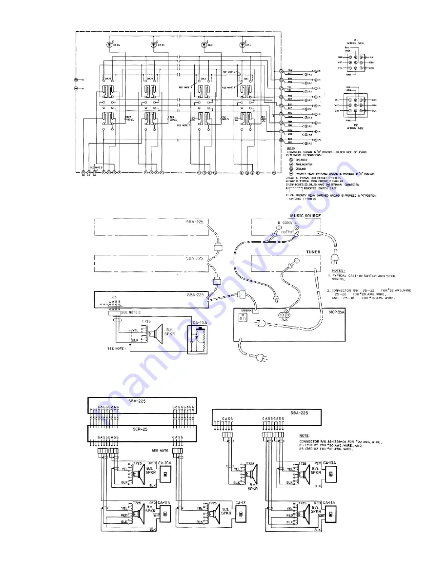
Figure 11– Schematic Diagram, SBA225 Room Selector Panel
Figure 12– Typical Interconnection Diagram
Figure 13– Typical Wiring Diagram
Страница 1: ...Specifications subject to change without notice 2010 Bogen Communications Inc All rights reserved 54 5871 03E 1004 MCP35A Master Control Panel Installation Use Manual ...
Страница 2: ... produce heat 9 Do not defeat the safety purpose of the polarized or grounding type plug A polarized plug has two blades with one wider than the other A grounding type plug has two blades and a third grounding prong The wide blade or the third prong are provided for your safety If the provided plug does not fit into your outlet consult an electrician for replacement of the obsolete outlet 10 Prote...
Страница 3: ...anel 5 External MIC for MIC 1 Console MIC Rear Panel 5 Time Tone Rear Panel 5 External Booster Amplifier Rear Panel 5 Remote Emergency Telephone Paging Rear Panel 5 Remote Emergency Microphone Paging Rear Panel 5 Associated Equipment 6 7 SBA225 Room Selector Panel 6 SBA225 Wiring 6 SCR25A Call In Module 6 SCR25A Installation 6 TWK351 Option 7 Staff Station Equipment 7 Call Origination Switches 7 A...
Страница 4: ...itches and can include privacy control to positively pre vent monitoring Provision is included for voice call in from stations equipped with voice call in switches The MCP35A control panel permits the user to Establish direct two way communication between the control panel and any speaker equipped location via a room selector panel and the press to talk release to listen push button while maintain...
Страница 5: ...o a station via the INTERCOM channel 3 2 6 7 3 4 5 9 11 8 1 Front Panel Rear Panel 1 Microphone Inputs A terminal strip provides connection for two low im pedance balanced microphones May optionally provide phantom power The console microphone is used as MIC 1 however this feature may be disabled Use two conductor shielded microphone cable 2 Voice Call In Connects parallel lines from station call ...
Страница 6: ...id electric shock be sure to disconnect AC Power Cord before removing the cover of the amplifier unit Warning DO NOT perform any function requiring the removal of the cover of the unit unless you are qualified to do so Gain Adjustments Internal Internal controls are provided to set the level of emergency page volume privacy tone volume and time tone volume These controls are factory set under norm...
Страница 7: ...d to the MIC 1 input see Fig 2 Time Tone Rear Panel A tone signal sounds through all speakers when the time clock terminal is grounded through a closure The tone may be used as a class change sig nal or for other purposes such as a telephone night ringer or alarm signal External Booster Amplifier Rear Panel Model BPA60 provides increased power output To install connect a cable terminated in a male...
Страница 8: ... using one female centerline plug to terminate wires from the speaker and or call switch Connect the shield to the ground terminal This is the only place where speaker cable shields should be grounded SCR25A Call In Module Caution The installation of accessory equipment requires the removal of protective covers exposure of internal components presents an electrical shock hazard Accessory equipment...
Страница 9: ...t monitoring See Figure 10 Appendix General Wiring Where possible locate the MCP35A centrally relative to the rooms being served in order to minimize the length of speaker cables Orient the unit so that the operator program director or other parties are able to see the controls at all times Provide adequate lighting and ventilation Do not locate the unit close to heat sources radiators warm air du...
Страница 10: ... are connected by a common control cable and one cable is run to the control panel If this type of installation is not practical the control cables for two or more switches are run to the control center and are connected in parallel at a junction box a single control cable is then run to the terminal strip at the rear of the MCP35A chassis Call Privacy Option Figure 10 shows the room connections a...
Страница 11: ...9 Figure 11 Schematic Diagram SBA225 Room Selector Panel Figure 12 Typical Interconnection Diagram Figure 13 Typical Wiring Diagram ...
Страница 12: ...een subjected to abuse misuse improper storage neglect accident improper installation or have been modified or repaired or altered in any manner whatsoever or where the serial number or date code has been removed or defaced THE FOREGOING LIMITED WARRANTY IS BOGENʼS SOLE AND EXCLUSIVE WARRANTY AND THE PURCHASERʼS SOLE AND EXCLUSIVE REMEDY BOGEN MAKES NO OTHER WARRANTIES OF ANY KIND EITHER EXPRESS O...