SX-16 Nightsun
®
Searchlight System
Maintenance Manual
Document 031734-1/Revision A
031734-1 Revision B
January 27, 2014
•
On the non-drive side of the Gimbal Arm, the threaded portion of the Wing Bolt projecting
outward from the spacer and arm bearing can be viewed. This portion of the Wing Bolt
screws into one of the Searchlight’s mounting bosses and extends through the Arm Bearing.
4.3.4
Azimuth Attachment and Movement
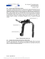
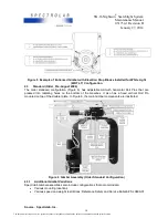
The Azimuth Gearbox and Motor are mounted at the top of the Gimbal arm (where it attaches to the
aircraft).
•
The Azimuth Gearbox has a shaft that secures the Searchlight to the aircraft mounting
bracket through four mounting bolts. This shaft supports the entire weight and aerodynamic
load of the Searchlight and Gimbal assembly.
•
A combination of fixed (cannot be adjusted) and Azimuth stops limit Searchlight motion to
prevent it from pointing in unwanted directions. These stops are located around the bottom of
the Azimuth Gearbox and on the top of the Gimbal Arm doubler plate.
4.4
Wing Bolts
The Wing Bolts on each side of the Gimbal yoke are stainless steel 5/16”-24 bolts, and they have
wing handles welded to the bolt heads.
•
A 1/16” diameter stainless steel wire rope (or lanyard) with a safety pin type clip on the free
end is permanently attached to each Wing Bolt. The clip is attached to a bracket on the side
of the Gimbal.
•
The lanyard helps to prevent the Wing Bolt from accidentally unfastening. It keeps the Wing
Bolt from being separated from the Gimbal when the Searchlight is removed. These also act
as safety cables for both Wing Bolts and ensure that the Wing Bolts cannot be separated
from the Gimbal or aircraft during flight.
4.4.1
Inspection
The Wing Bolts should be inspected during preflight (or daily) inspection. They also should be
inspected every 6 months or 300 flight hours or 100 operation hours. Use the following inspection
procedures:
•
Daily:
o
Verify that both Wing Bolts are in place and that the lanyards are connected to the angle clips
on the Gimbal.
o
Verify that both Wing Bolts are fully hand tight. If not, tighten them.
o
Verify that the hairpin clip on the lanyard is properly closed and secure.
o
Verify that the lanyards do not have more than 10% of the wire strands broken. If they are
broken or if many sharp individual wires are sticking out, replace the Wing Bolt and lanyard.
•
Every 6 months or 300 flight hours or 100 operation hours, loosen the lanyard and try to unscrew
both Wing Bolts, one at a time.
•
The locking feature (which is part of the threaded insert into which the Wing Bolt is screwed)
should resist the attempt to unscrew the Wing Bolts. Resistance, however, should be moderate;
you should be able to unscrew the Wing Bolt without a wrench. If there is moderate resistance,
the Wing Bolt is fine. When you re-insert the bolt, lubricate the bolt lightly to minimize future
galling and insert wear.
•
If there is heavy resistance, the Wing Bolt threads are probably damaged or partially galled; the
Wing Bolt must be replaced. If there is no resistance, the Searchlight threaded insert is probably
worn out and must be replaced. The replacement procedures for the insert and the bolt are in
Test of Wing Bolt Housing Boss Inserts
section of this manual.
4.5
Gimbal Wiring
4.5.1
Inspection Schedule
The Gimbal wiring is exposed to the outdoor environment, to flight aerodynamics such as wind and
rotor downwash, and the flexing and abrasion associated with the Azimuth (left-right) motion of the
Gimbal (while the Gearbox housing and connector mount remains stationary). Consequently, the
wiring should be inspected daily (preflight) and every 3 months or 100 flight hours or 50 operating
hours.
Source: Spectrolab, Inc.
12
The document reference is online, please check the correspondence between the online documentation and the printed version.


