INSTALLATION INSTRUCTIONS
Page 2 of 8
1.
Remove the license plate and bracket. Models with active automatic air dam, unplug and remove air
dam from bottom of frame.
2.
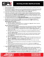
On the driver/left side of the bumper, remove the (2) factory bolts attaching the inner plastic cover to the
side of the frame,
(Figure 1)
. Next remove the outer bolts attaching the cover to the end of the bumper
and remove the inner plastic cover. Repeat this
Step
to remove the passenger/right cover.
3.
Locate and unplug all wire harnesses leading to the front bumper,
(Figure 2)
.
4.
Place blocks or jack stands under the bumper to support it during mounting bolt removal. Once the
bumper has been safely supported, remove the (3) factory flange nuts attaching each bumper bracket
to the end of the frame,
(Figures 2 & 3)
.
WARNING!
Assistance is required to hold bumper in place
during hardware removal to prevent the bumper from falling. Slide the bumper assembly off of the end
of the frame and place bumper on a stable, clean surface.
5.
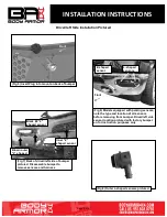
On models equipped with tow hooks,
loosen but do not remove
the inner rear tow hook/body mount
bolt. Remove the forward mounting bolt and slide tow hook off of the bottom of the frame,
(Figure 4)
.
Repeat to remove remaining tow hook.
NOTE
: Tow hooks cannot be reinstalled with Bumper.
6.
Determine if the vehicle is equipped with front bumper parking sensors.
NOTE
: Sensors must be
installed before installing Bumper Assembly.
Models without front sensors:
a.
Select the included (6) Rubber Plugs.
b.
From behind bumper, push plugs into sensor mounting holes,
(Figure 5)
. Screws have been
provided to lock the plugs in the sleeve. Use is optional.
Models equipped with front sensors:
a.
Disassemble the front bumper to unplug and remove the wiring harness. Remove the driver/left
outer sensor first.
IMPORTANT
: The front bumper is equipped with (2) outer brown “L” shaped
sensors, (2) #2 location black “L” shaped sensors (2) inner “Z” shaped sensors. Pay close
attention to the location and type of all sensors for correct reinstallation,
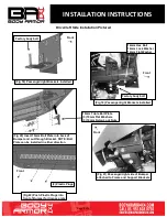
(Figures 6 & 7)
. Install
sensors one at a time.
b.
Starting with the #1 driver/left outer “L” shaped sensor, remove the sealing washer from the
front of the sensor. Select (1) Sensor Foam Washer. Push the Foam Washer onto the front of
the sensor,
(Figures 8 & 9)
.
c.
Slide the sensor into the #1 driver/left outer sensor mount on the Body Armor Bumper. Attach
(1) Foam Spacer to (1) Retaining Clip. Push the Retaining Clip into the holes in the sensor
mount,
(Figure 10)
.
d.
Repeat the above steps to attach the #2 “L” sensor.
e.
Next, repeat the previous Steps to install (1) “Z” shaped sensor into the #3 inner sensor mount,
(Figure 9)
.
IMPORTANT:
The (2) “Z” shaped sensors attach to the
inner
sensor mounts and
the (4) “L” shaped sensors attach to the
outer
sensor mounts only.
f.
Repeat the previous Steps to install the remaining sensors in the correct sensor mounting
locations.
g.
Run the wire harness through the sensor openings on the bumper to connect the wire harness
to each sensor.
h.
Attach the (2) Wire Harness Extensions to the (2) inner “Z” shaped sensors.
NOTE
: Wire
harness extensions can only be used with the inner “Z” shaped sensors. Use the included Wire
Ties to attach the harness to the Bumper.
7. Center LED light installation
(light sold separately).
a.
Select the “L” Brackets,
(Figure 11)
. Attach the Brackets to the top of the (2) mounting tabs
welded onto the back of the bumper with the included (2) 8mm x 25mm Hex Bolts, (4) 8mm Flat
Washers, (2) 8mm Lock Washers and (2) 8mm Hex Nuts. Leave loose at this time.
b.
Attach the LED light assembly to the “L” Brackets with the included (2) 8mm x 16mm Hex Bolts,
(2) 8mm Lock Washers and (2) 8mm Flat Washers,
(Figure 11)
. Do not fully tighten hardware at
this time.
IMPORTANT
: “L” Brackets are designed for 8mm light mounting hardware only.


