

Failure Status will be reset when the unit passes:
• The next automatic test, or
• Briefly pressing the 2W-ITS, or
• A power failure exceeding 10 seconds.
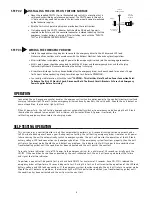
NOTE:
The unit engage connector pins must be connected for the emergency driver and AC driver to
operate normally.
4
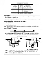
EMERGENCY DRIVER AND AC DRIVER MUST BE FED FROM THE SAME BRANCH CIRCUIT
TYPICAL SCHEMATICS ONLY. MAY BE USED WITH OTHER DRIVERS. CONSULT THE FACTORY FOR OTHER WIRING DIAGRAMS.
WIRING DIAGRAMS
NOTE 1:
For short-term testing of the emergency function, the battery must be charged for at least one hour.
The emergency driver must be charged for at least 24 hours before conducting a long-term test.
NOTE 2:
Connections with * are Class 2 rated outputs.
Connections with # are Class 2 rated inputs only.
TCASE TEST POINT LOCATION
WITH THERMAL PROTECTOR
AC LED
DRIVER
LED +
LED -
GROUND
NEUTRAL
LINE
WALL
SWITCH
UNSWITCHED HOT
WHITE
(-)
(+)
BLACK
GRAY
BLUE #
BLACK
RED
BLACK #
GREEN
NEUTRAL
GROUND
WHITE
GRAY
GRAY
*
*
*
LED
LOAD
L
E
D
D
R
I
V
E
R
E
M
E
R
G
E
N
C
Y
UNIT
ENGAGE
GRAY
VIOLET
VIOLET
BROWN
BROWN
2W-ITS
*
*
*
BLUE
WHITE
BLACK
THERMAL
PROTECTOR
AC LED
DRIVER
WALL
SWITCH
UNSWITCHED HOT
WHITE
(-)
LED +
(+)
BLACK
GRAY
BLUE #
BLACK
RED
BLACK #
LED -
GREEN
NEUTRAL
GROUND
WHITE
GRAY
GROUND
NEUTRAL
LINE
GRAY
*
*
*
LED
LOAD
L
E
D
D
R
I
V
E
R
E
M
E
R
G
E
N
C
Y
UNIT
ENGAGE
GRAY
VIOLET
VIOLET
BROWN
BROWN
2W-ITS
*
*
*
0.59" (15 mm)
Tc
212 mm(8.03
")
MAINTENANCE
This self testing emergency driver automatically performs required routine testing. Results are reported to
maintenance personnel via the indicator light.
Note:
Maintenance personnel should periodically check the indicator light. If the indicator light is flashing, follow steps
in the
Troubleshooting Guide
.
TROUBLESHOOTING GUIDE
STATUS INDICATOR
LIGHT
PROBLEM
CORRECTIVE ACTION
Light on not flashing
None
None, Unit is Operating Correctly.
Flashing 2 times every 5 seconds
Battery Error
Charge battery. If after an hour failure is
still indicated, see action below.
Flashing 3 times every 5 seconds
Charging Error
Ensure input wiring is correct and verify voltage is
correct and stable.
Flashing 4 times every 5 seconds
Output Error
1. Output might be either open or short circuited.
2.
Ensure
that fixture wiring is in accordance with
proper wiring diagram.
3.
Ensure
connections to the LED load.
Continuous Flashing
Application out
of range
Ensure LED load is operational and specified
for self-testing emergency driver


