

INSTALLATION
22
NOTE:
Make sure the necessary branch circuit wiring is available. An unswitched source of power is
required. The emergency driver must be fed from the same branch circuit as the AC driver.
CAUTION: DO NOT JOIN UNIT ENGAGE CONNECTOR UNTIL INSTALLATION IS COMPLETE AND AC POWER IS
SUPPLIED TO THE EMERGENCY DRIVER.
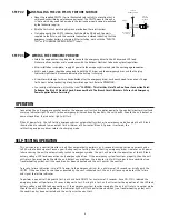
STEP #1
INSTALLING THE EMERGENCY DRIVER
> Disconnect AC power from the LED luminaire.
> Mount the emergency LED driver by the mounting tabs using the supplied screws. The luminaire’s installation
instructions may provide guidance on the recommended mounting location.
>
Mounting Height:
Many factors influence emergency illumination levels, such as the lamp load selected, luminare
design, and environmental factors therefore end use verification is necessary. For field installations, when the attached
luminaire is mounted at heights greater than 7.17ft (2.2m), the level of illumination must be measured in the end
application to ensure the requirements of NFPA 101 and local codes are satisfied.
>
Remote Mounting:
The emergency LED driver may be remote mounted from the luminaire it enclosed and installed in
accordanance with the NEC. If used in conjunction with an AC driver the allowed distance is up to half the distance the
AC driver manufacturer recommends remote mounting the AC driver from the LED load. If used without an AC driver, and
remote mounting more than 5 feet from the luminaire, please consult the factory to determine the necessary wire gauge.
CAUTION:
Remote mounting can result in reduced power output.
Lumens In Emergency Mode = Lumens per Watt of Fixture * Output Power of Chosen Product
________________
(Lumens)
_ = __________________
(lm/W)
_* ________6______(
W)
_
1. Ensure the LED load’s rated power is greater than or equal to the power output of this emergency LED driver. This is to
ensure that this emergency product will not produce more power than the LED load can handle, thus ensuring that the
LED load will not be damaged when the system is in the emergency mode.
2. Verify that the forward voltage of the luminaire’s LED array is within the limits of this emergency LED driver. The forward
voltage of the LED array is commonly designated as Vf and should be found on the luminaire markings, in the luminaire
specifications, or imprinted directly on the LED arrays. If multiple LED arrays are to be driven, verify that the total
forward voltage is within the limits of this product. Using a voltage meter, it may be possible to directly measure the
voltage across the LED arrays when operating from the AC driver.
3. Ensure the output current of the AC LED driver does not exceed 5.0 Amps. This is the current into the blue wire connector.
4. Ensure there will be sufficient light output in the end application. Estimate the egress lighting illumination levels by
doing the following:
a. Find the efficacy of the LED load. This can be given by the luminaire manufacture. This number will be given in
lumens per watt (lm/w). It is the installer’s responsibility to validate the luminaire manufacturer’s efficacy data.
This can be accomplished by direct measurement, by review of independent 3rd party test data (UL, ETL, etc.),
accessing a public database of 3rd party data (such as Design Lights Consortium, www.designlights.org), or other
comparable
means.
b. Lumens can be calculated by multiplying the output power of the emergency LED driver by the efficacy of the LED
load. In many cases the actual lumen output in emergency mode will be greater than this calculation gives, however
it will provide a good estimate for beginning the lighting design of the system.
C. Using the results of this calculation and industry standard lighting design tools, calculate the anticipated
illumination levels in the path of egress.
This product is suitable for field installation with suitable LED loads including LED luminaires, DC voltage driven LED
replacements for fluorescent lamps and others. There are four (4) checks to determine if your luminaire is eligible for field
installation.
NOTE:
This product has been designed to reliably interface with a wide selection of LED loads and is electrically compatible
with every simple LED array that meets criteria 1 and 2 above. However, compatibility cannot be guaranteed with all current
and future LED systems. Compatibility testing of the end-use system is suggested. Please contact the factory with any
questions.
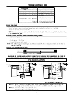
Installation of this emergency LED driver will vary based on the luminaire type, however, generally
follow these steps:
NOTE:
After installation, it will be necessary to measure the egress lighting illumination levels to ensure it complies with
national, state, and local code requirements.


