15
II - Installation of products
Select the location where the IP Buttons Box will be installed by making sure of the presence of
the network cable PoE (Plan the routing of the cable in the back or by the bottom of the product).
Warning:
when feeding the cables through the bottom, we recommend the use of a wire molding
(25x30mm min.) to cover the hole at the bottom of the casing.
2.1 IP Buttons Box
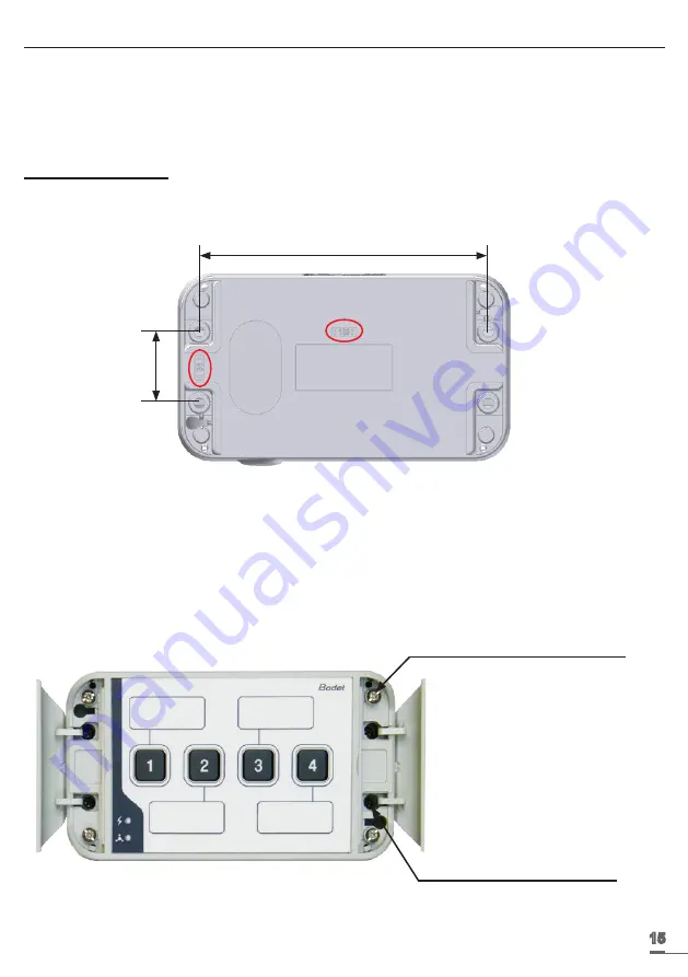
1/ Drill 4 holes for wall mounting according to the following pattern.
(The drilling dimensions are printed on the back of the housing).
IP Buttons Box or 4-buttons extension box - back view
2/ Open the flaps at each end of the product.
3/ Mount the box to the wall (B), taking care to get the Ethernet cable into the housing (cable from
the back or bottom of the housing Buttons IP).
4/ Open the casing by removing the 4 screws (A). The front cover is held by straps allowing it to
hang down when opened.
IP Buttons Box - front view
139
34
(A) Screws to open the case (x4)
(B) Wall mounting screws (x4)


